SGI Origin 3400
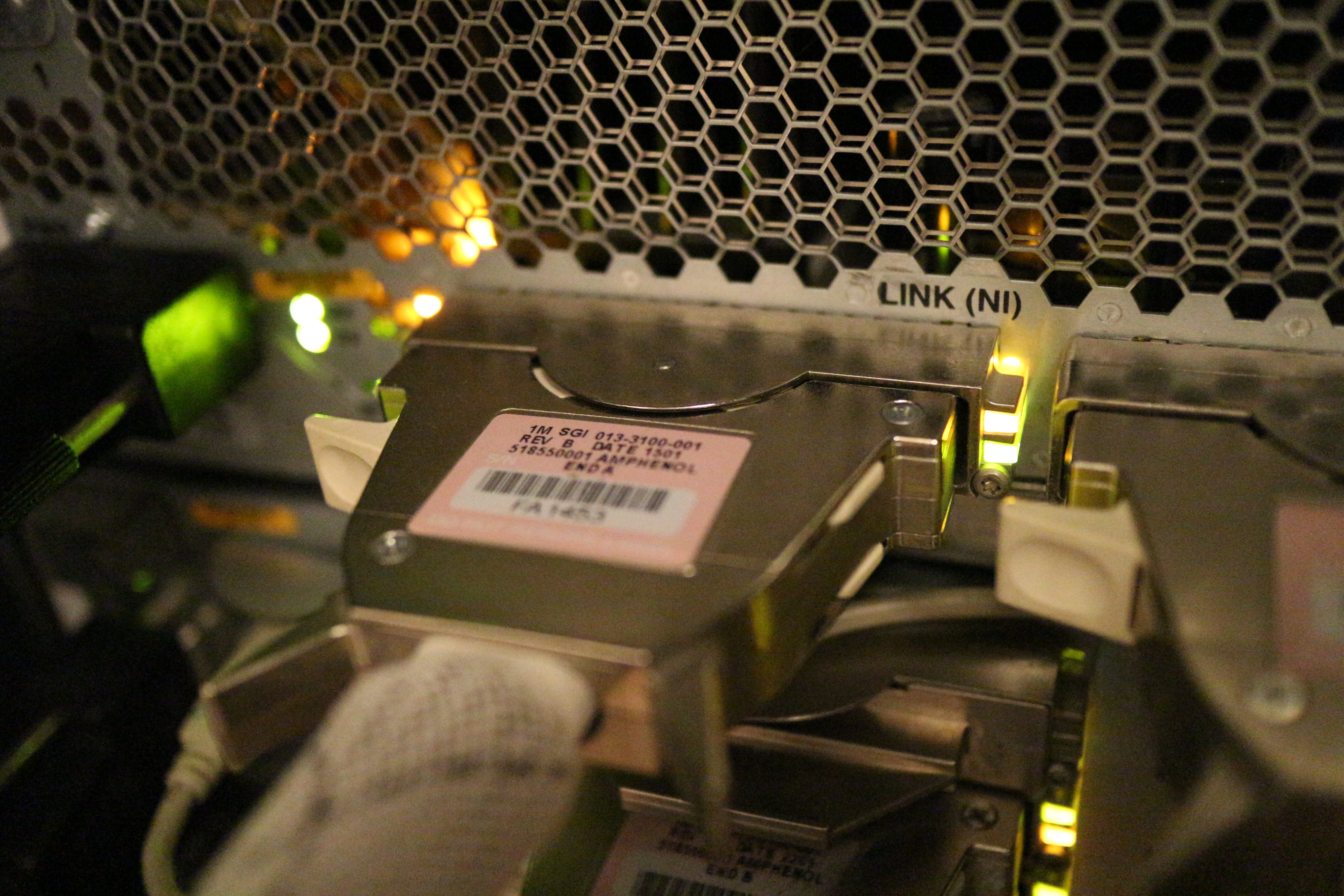
The Silicon Graphics Origin 3000 series machines are modular single-system-image (distributed shared memory) supercomputers, released in the year 2000. They're scalable from 2 to 512 processors and from 1GB to 1TB of RAM. The interconnect between nodes is SGI's proprietary NUMAlink3, which offers very low latency (1 microsecond for MPI messages, 50 nanoseconds round-trip for raw NUMAlink packets) and high bandwidth (1.6 GBytes/s in one direction). The topology of the entire system is a fat bristled hypercube.
Table of contents
- General description
- Block diagram of the Origin 3400
- Common hardware issues
- Replacing batteries
- Dealing with faulty DS1780 chips
- "No L1 comm!" error
- "enet_ssram: ssram address walk error"
- Replacing faulty RAM
- R-brick serial number mismatches
- My Origin 3400
- Output of hinv
- Output of scsimon
- Pictures
- Documents
- Acknowledgements
General description ↵^
Each Origin system consists of multiple different "bricks" (that is the official terminology), the following types are available:
| Name | Diagram | Back panel | Description |
|---|---|---|---|
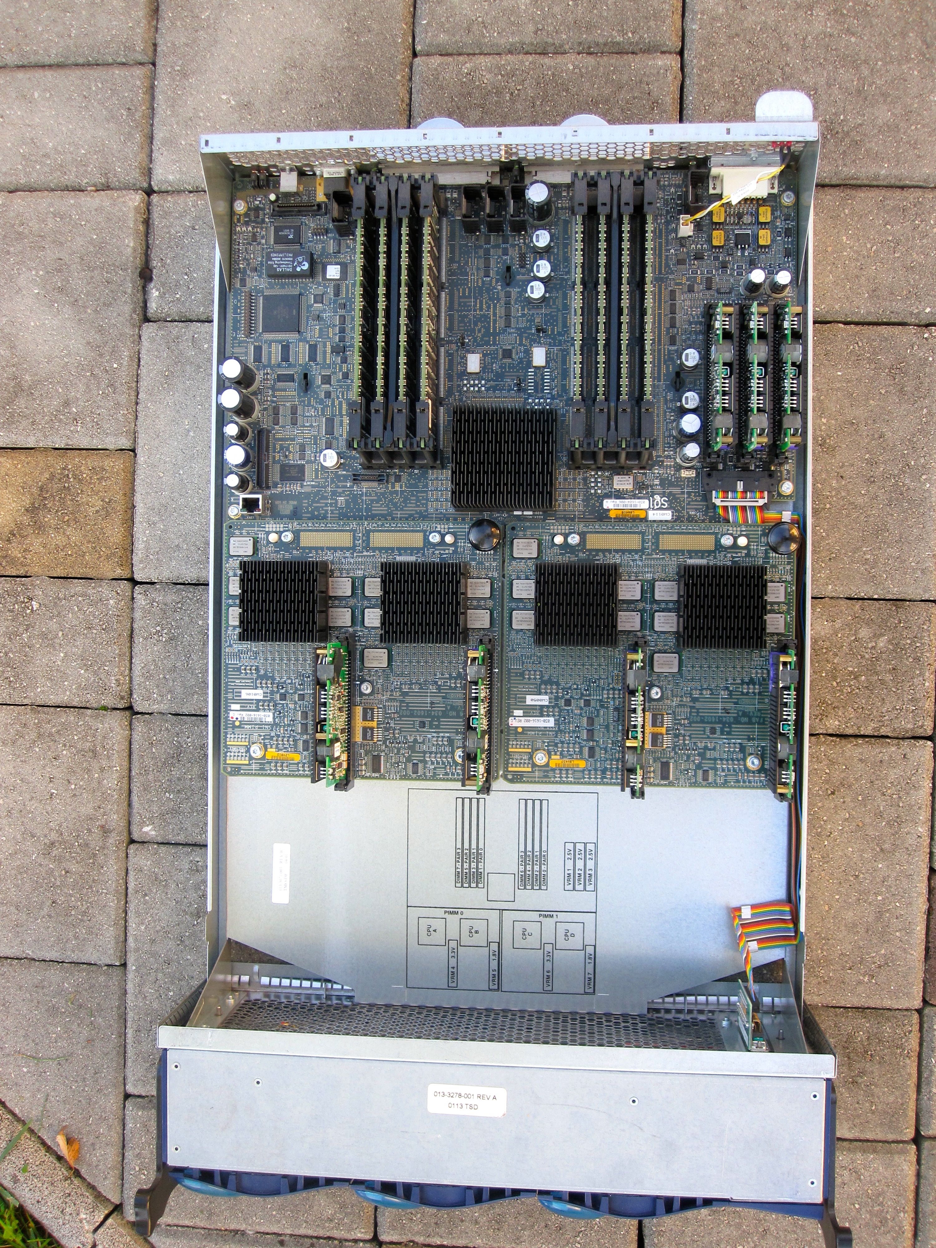
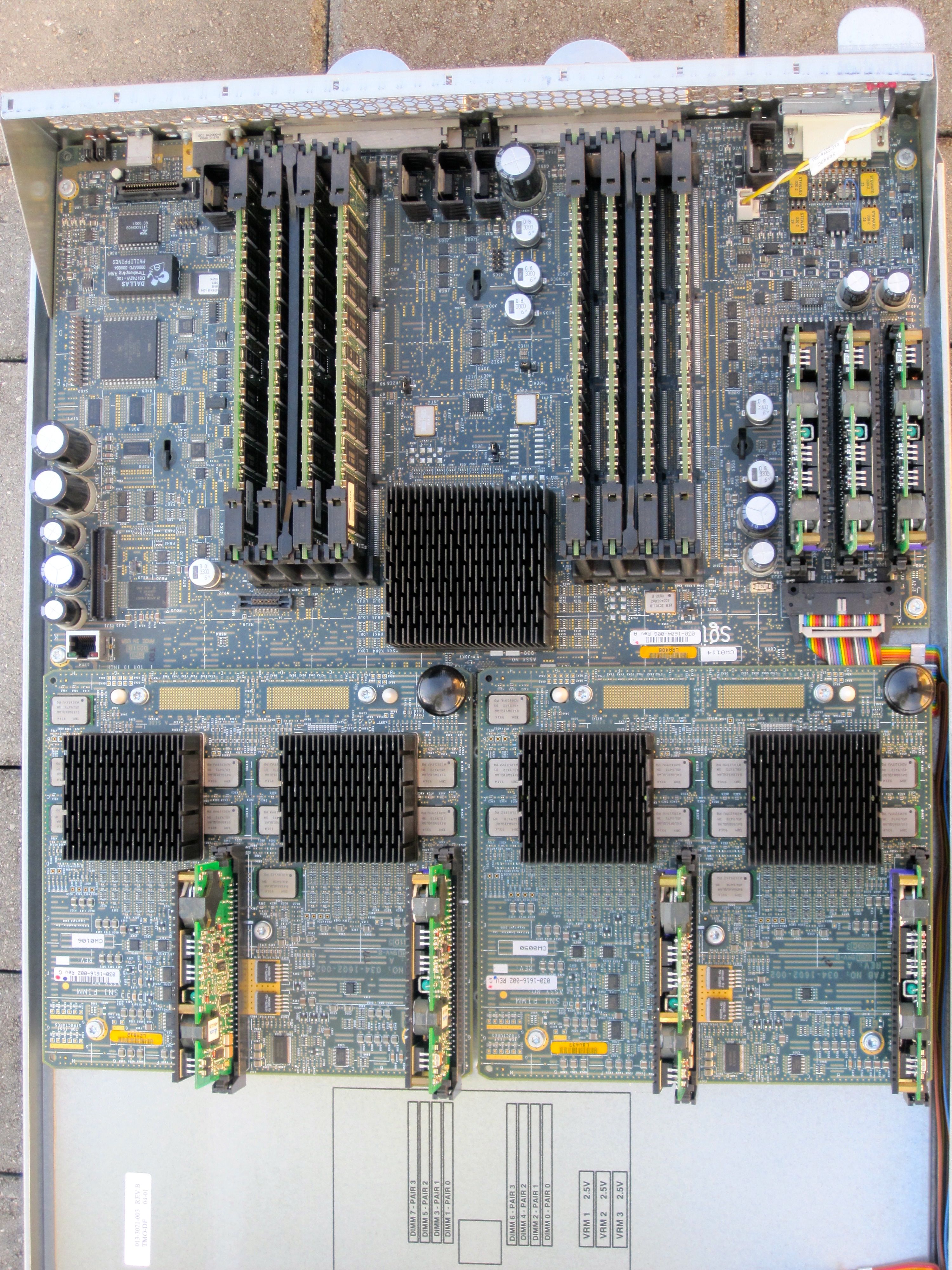
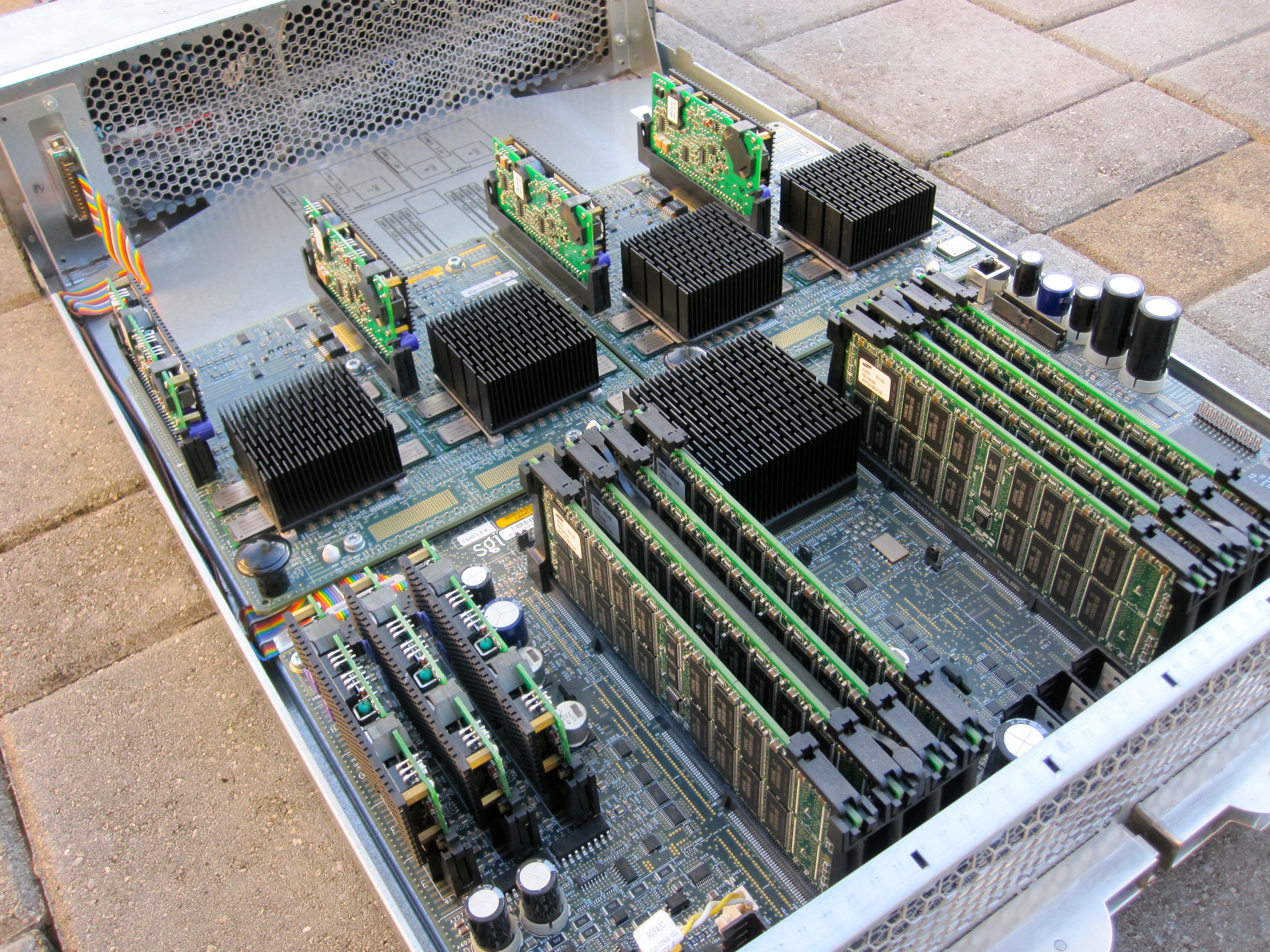
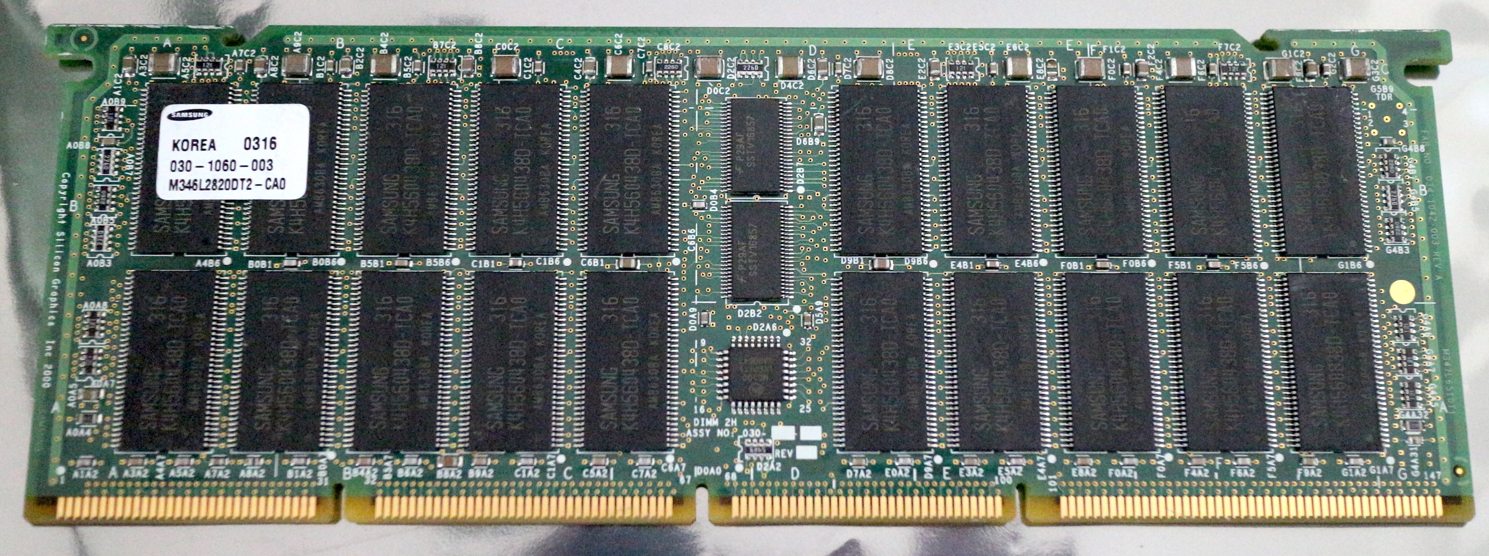
| C-brick |  |  | Contains up to 4 processors and 8GB of RAM. It's possible to mix different CPU types and speeds within the system, but not within a single C-brick. |
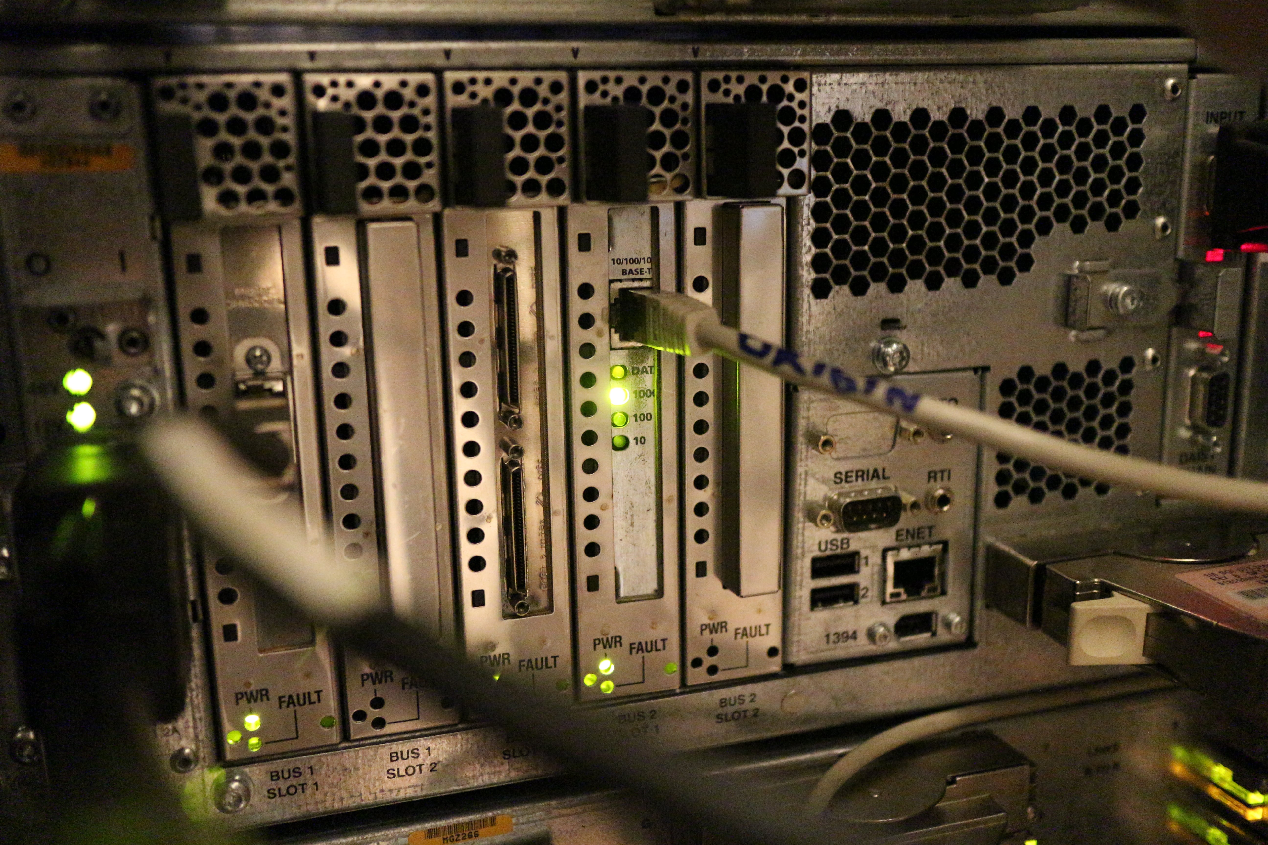
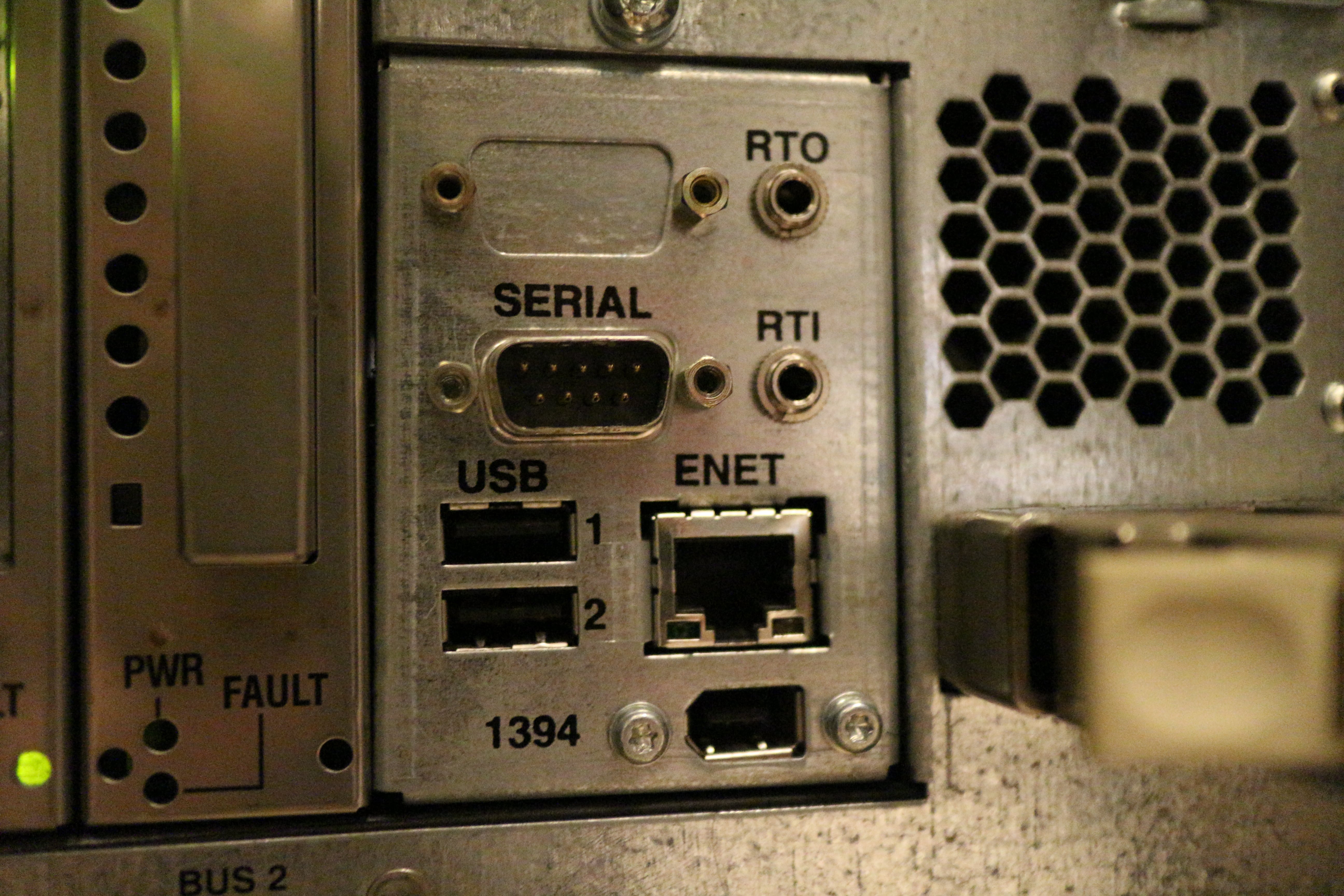
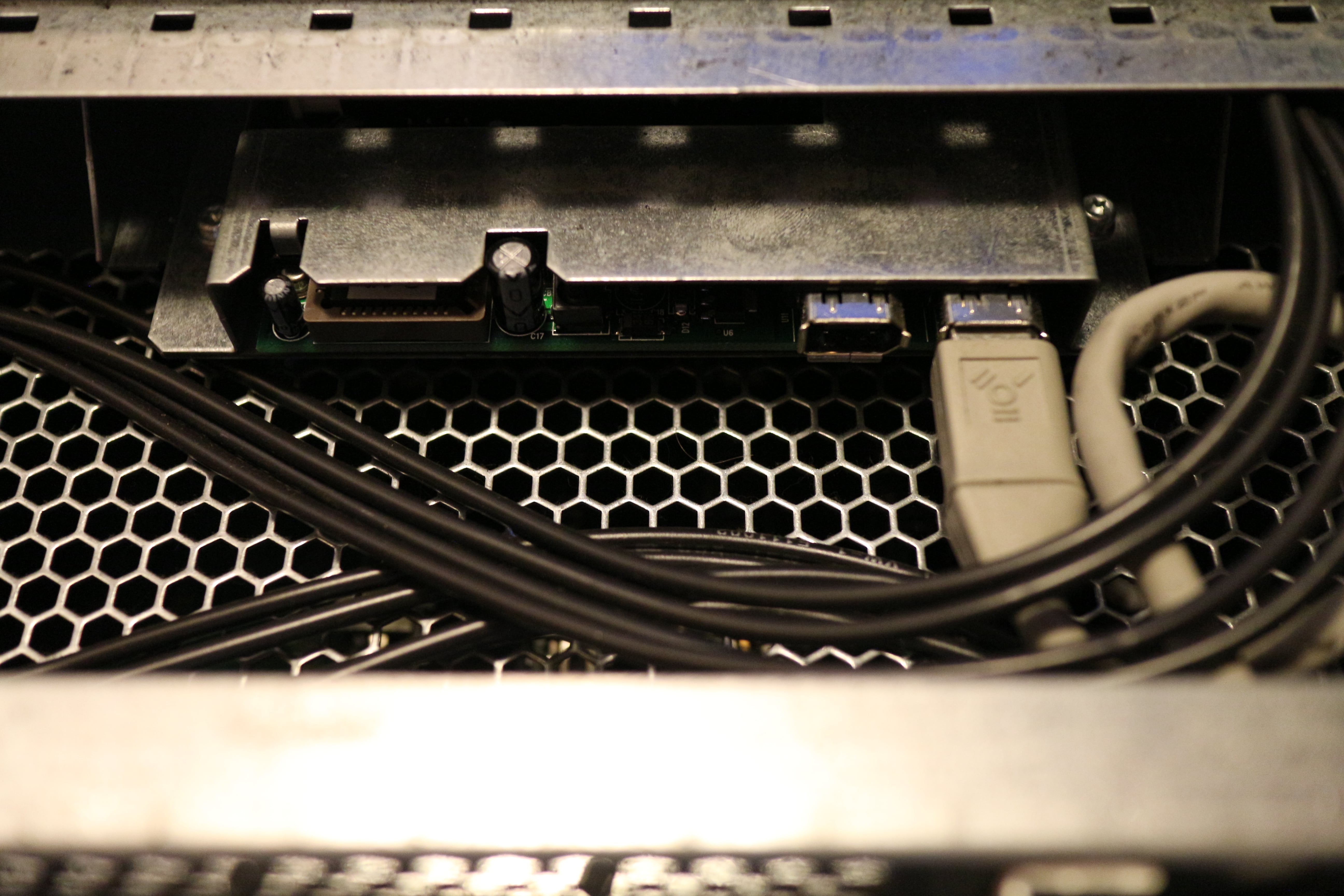
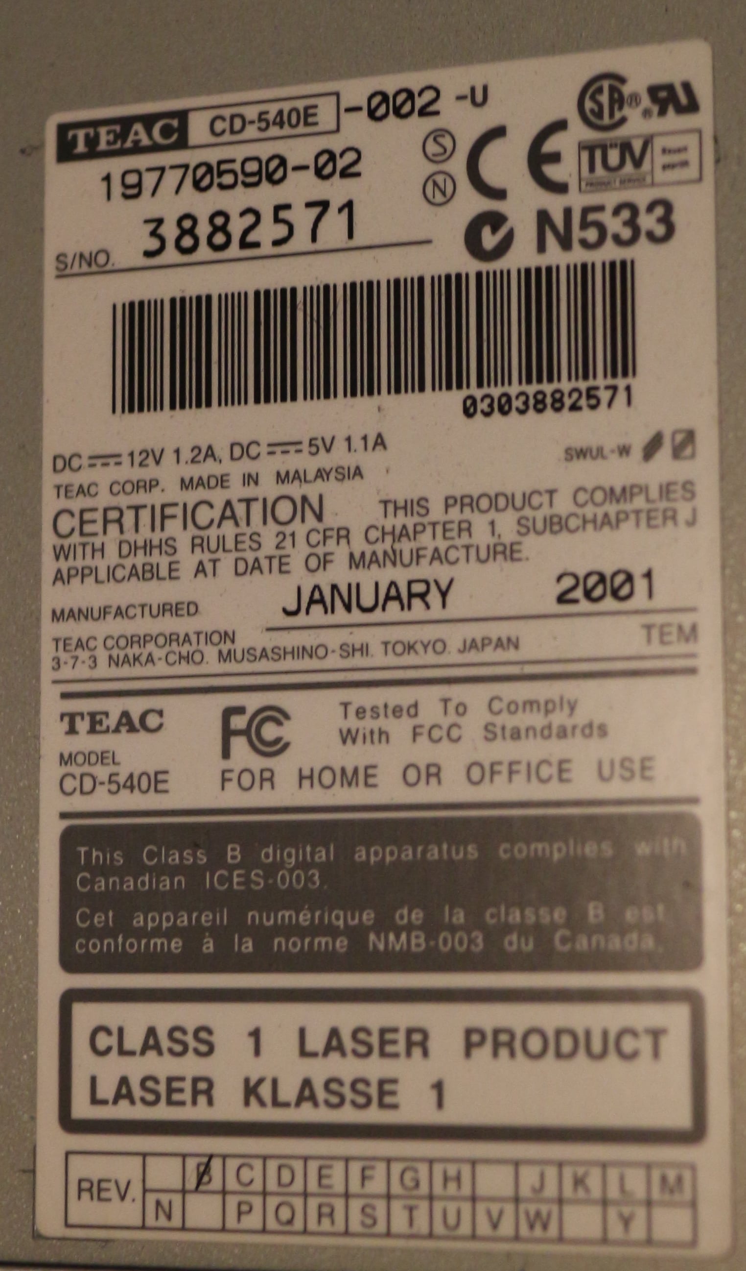
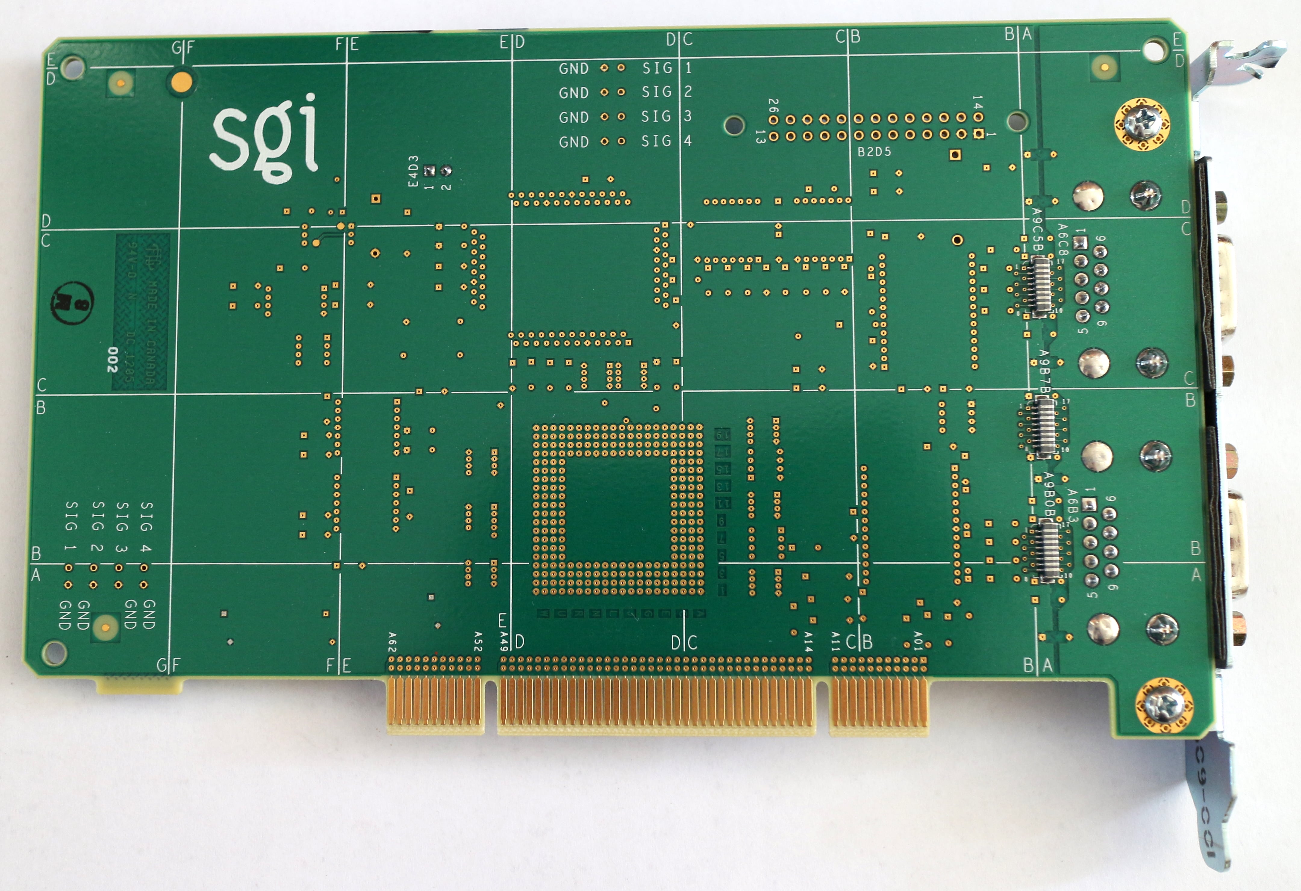
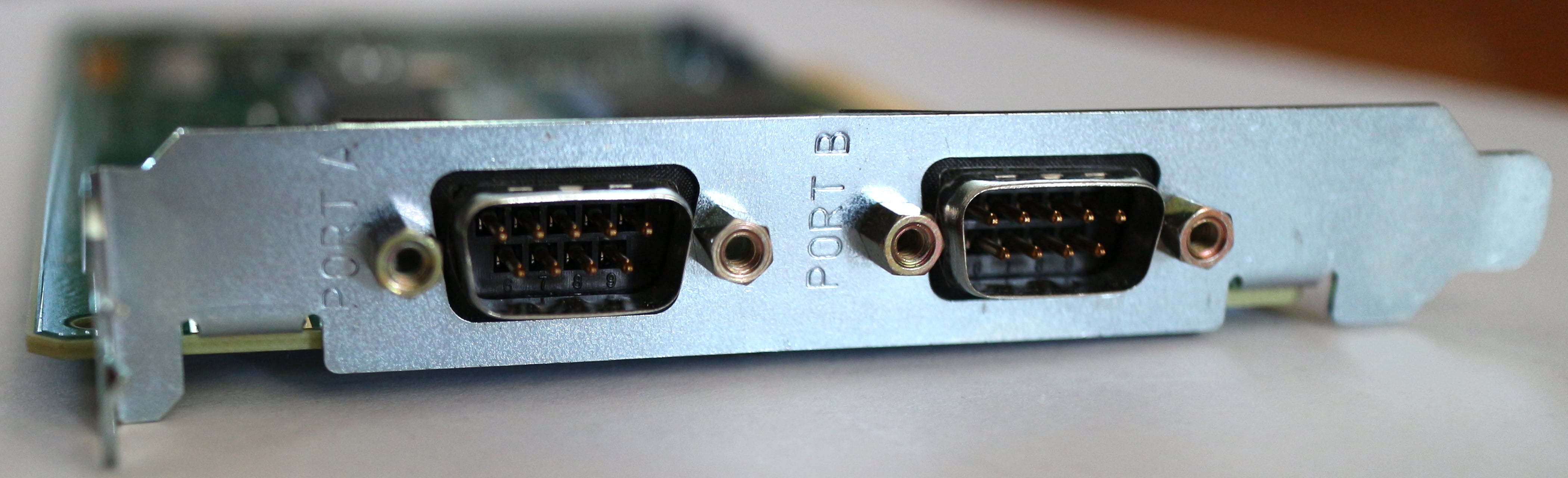
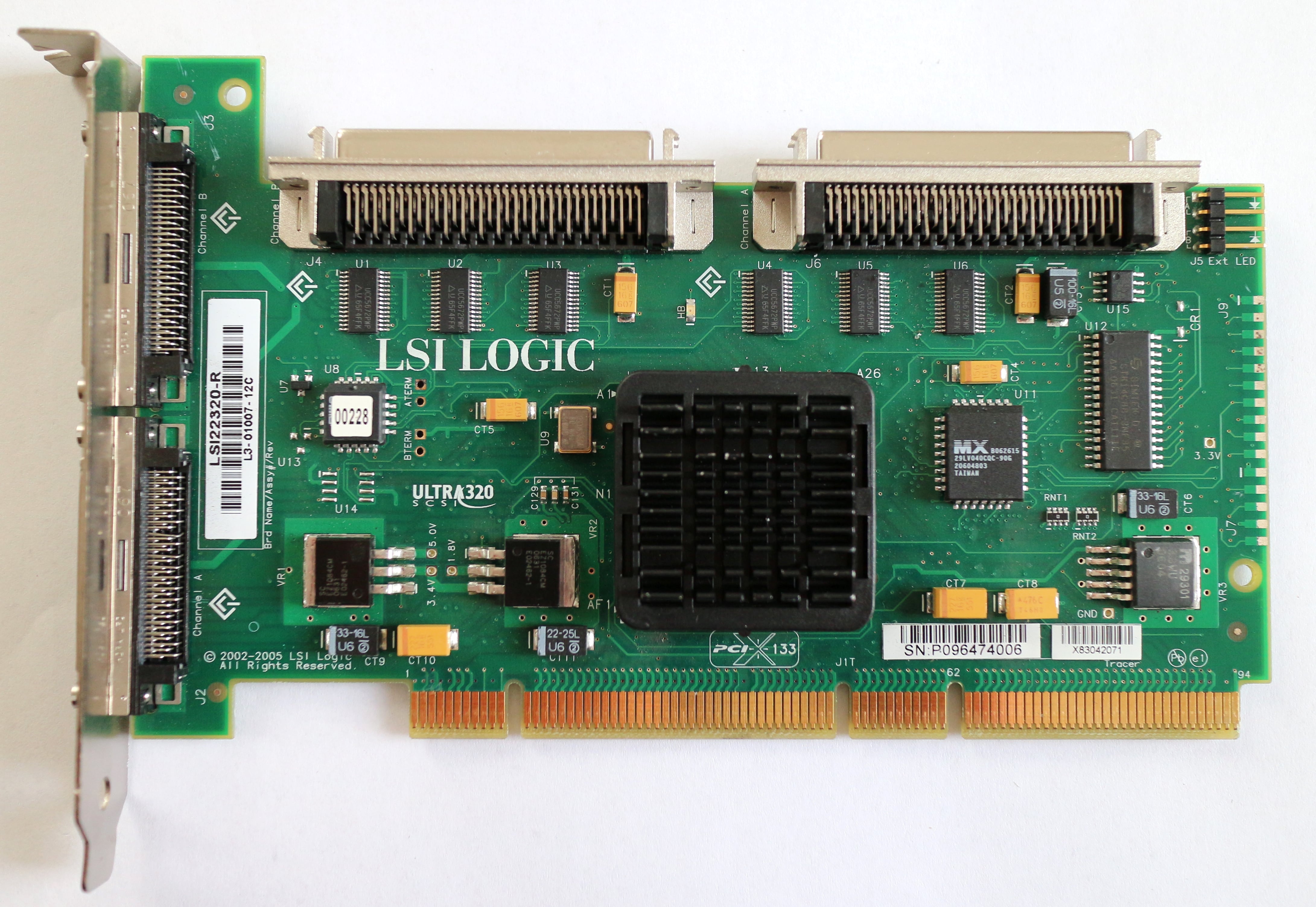
| I-brick |  |  | Provides basic I/O: 10/100 ethernet, two fibre-channel disks, CD-ROM drive (TEAC CD-540E, connected via a FireWire-to-IDE adapter), five hot-pluggable 64-bit PCI slots (on two busses, 2x 66MHz + 3x 33MHz slots), two USB ports, and a FireWire (IEEE-1394) port. |
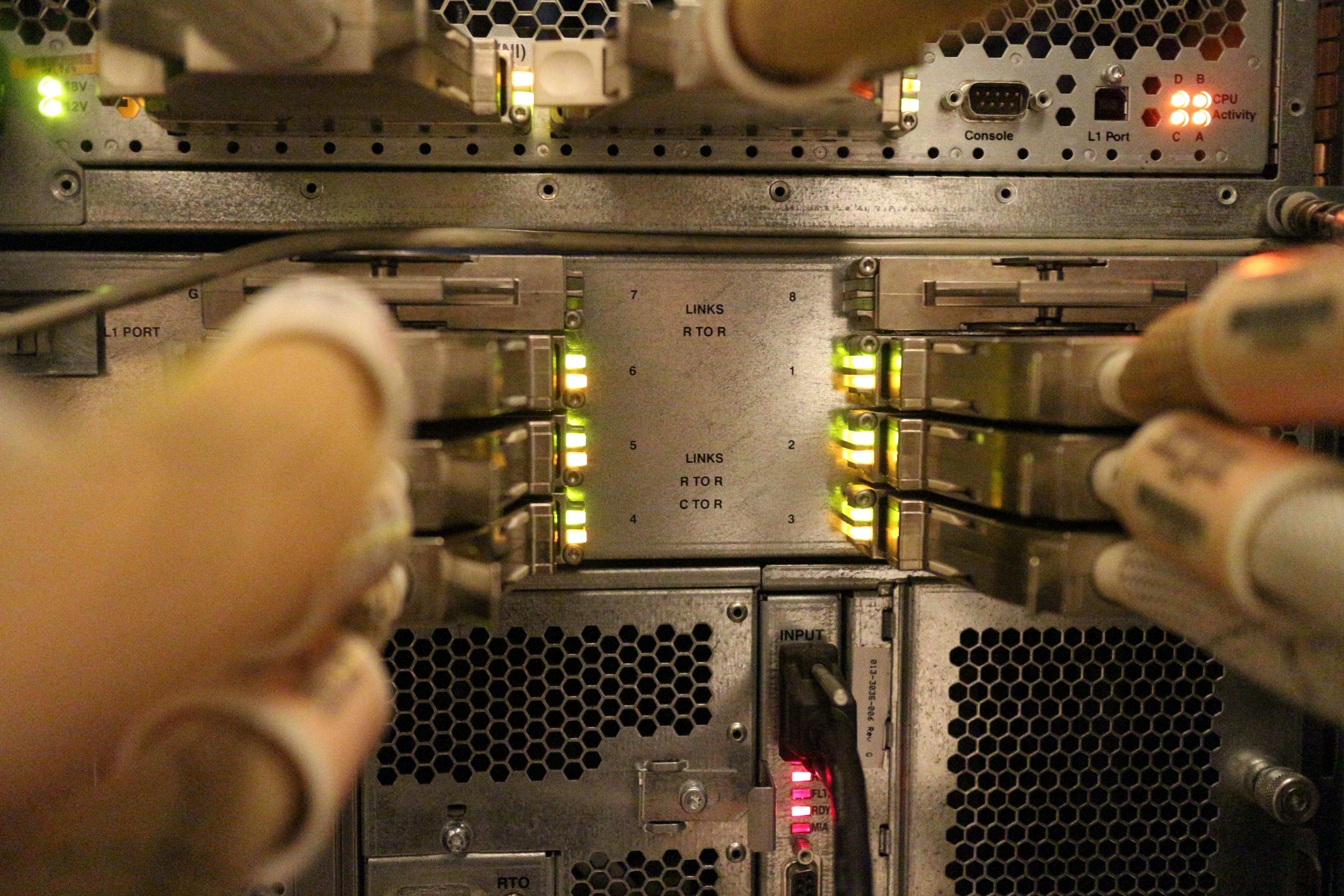
| R-brick |  |  | Provides routing between C-bricks in systems with more than two C-bricks (there are 6- and 8-port versions of the router brick). |
| P-brick |  |  | Provides an additional 12 hot-pluggable PCI slots (on 6 busses). |
| X-brick |  |  | Provides four XIO expansion slots (XIO is SGI's proprietary expansion interface used in their previous line of Origin 2000, Onyx2, and Octane systems). |
| G-brick |  |  | Provides graphics (this brick is the only difference between an Origin 3000 and an Onyx 3000). Each G-brick supports one or two InfiniteReality pipes (sets of boards). |
| V-brick |  |  | Provides lower-end graphics (an Onyx 3000 can have either one or more G-bricks or one or more V-bricks, but not both). Each V-brick supports one or two InfinitePerformance pipes, each pipe consists of a VPro V12 graphics board (also available in workstations). |
| N-brick |  |  | Connects four C-bricks to four G-bricks (useful if you don't need the extra I/O of I- and X-bricks that would have been used for this purpose instead). |
| D-brick |  |  | Provides disk storage (twelve hot-pluggable fibre-channel drives, no RAID). |
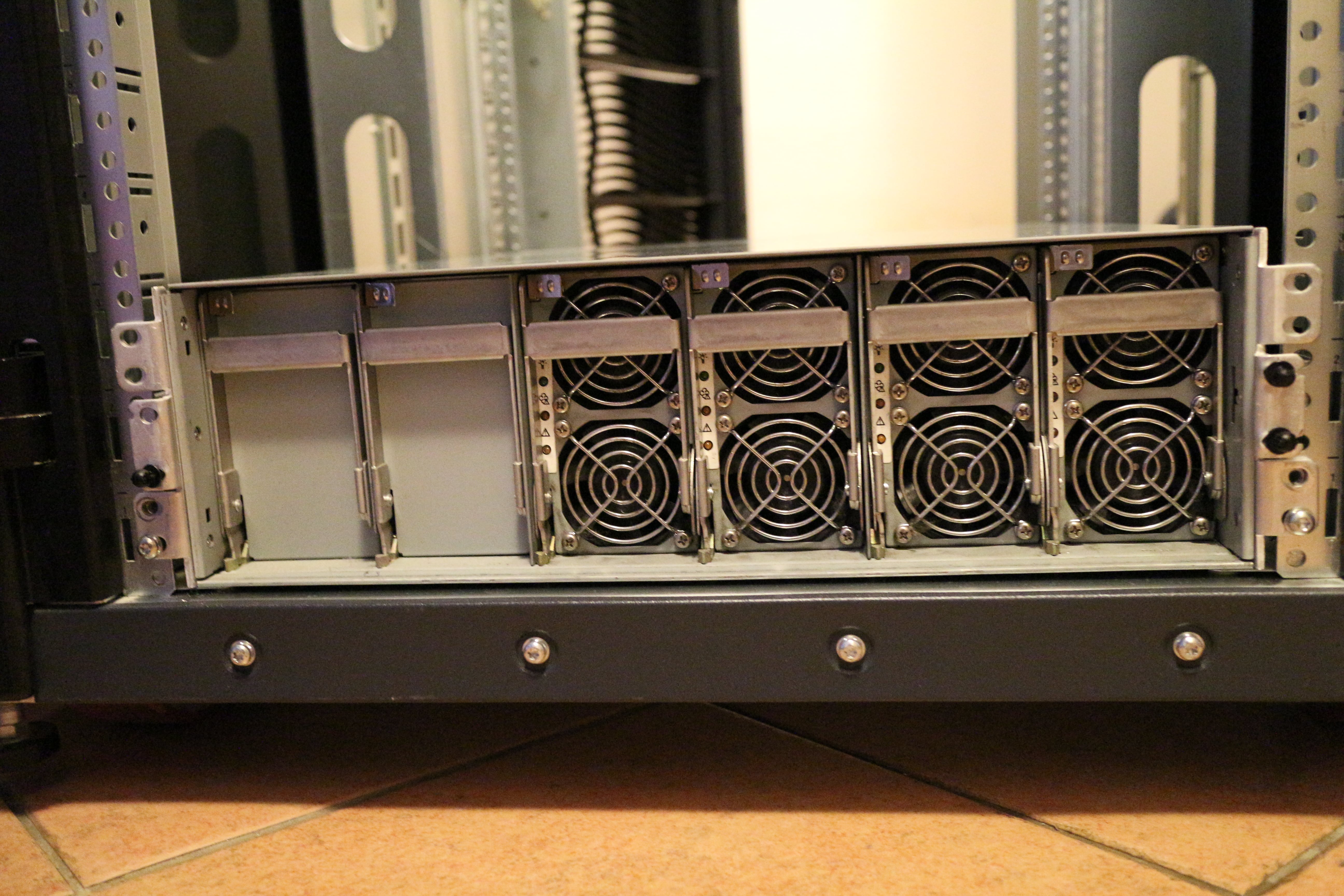
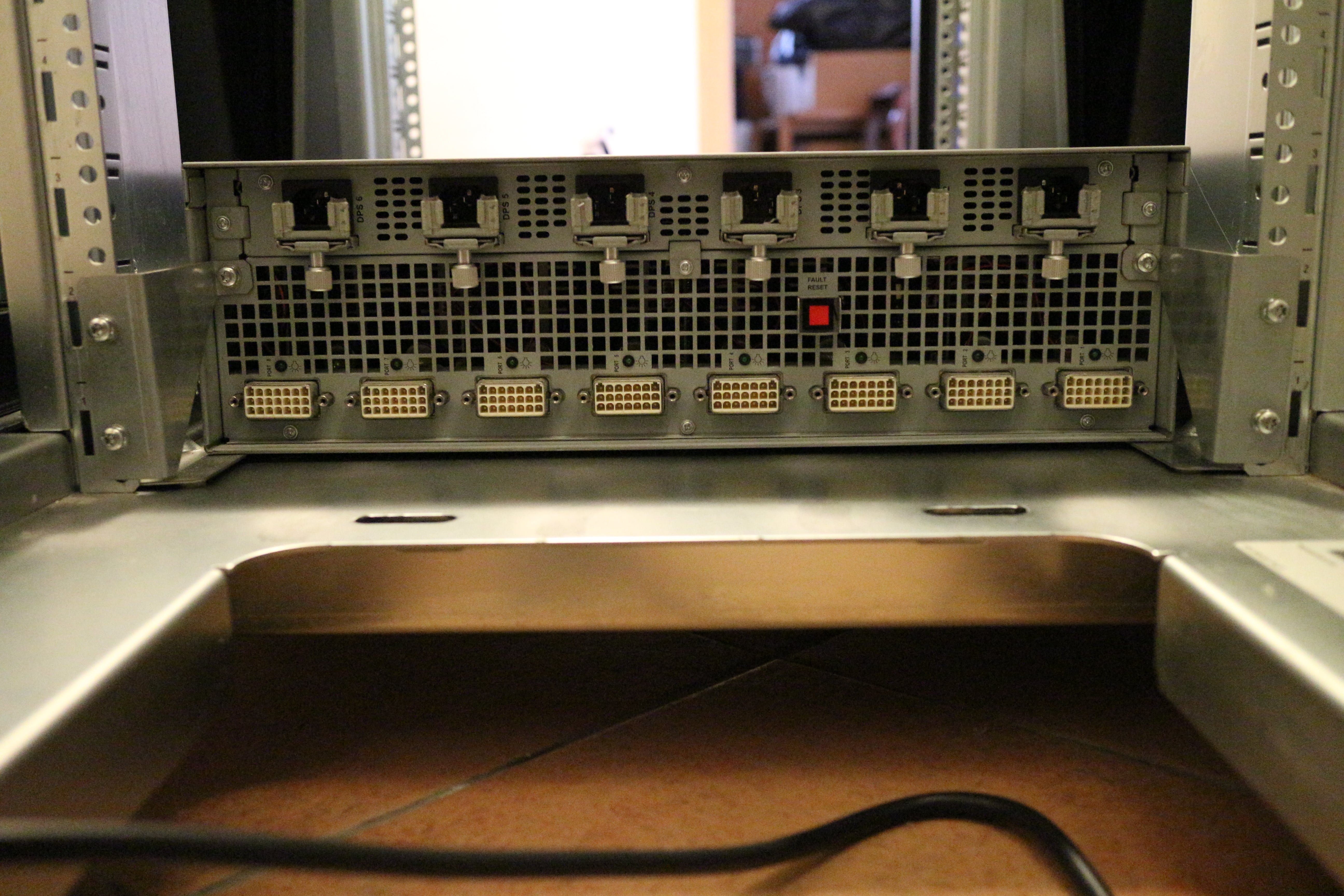
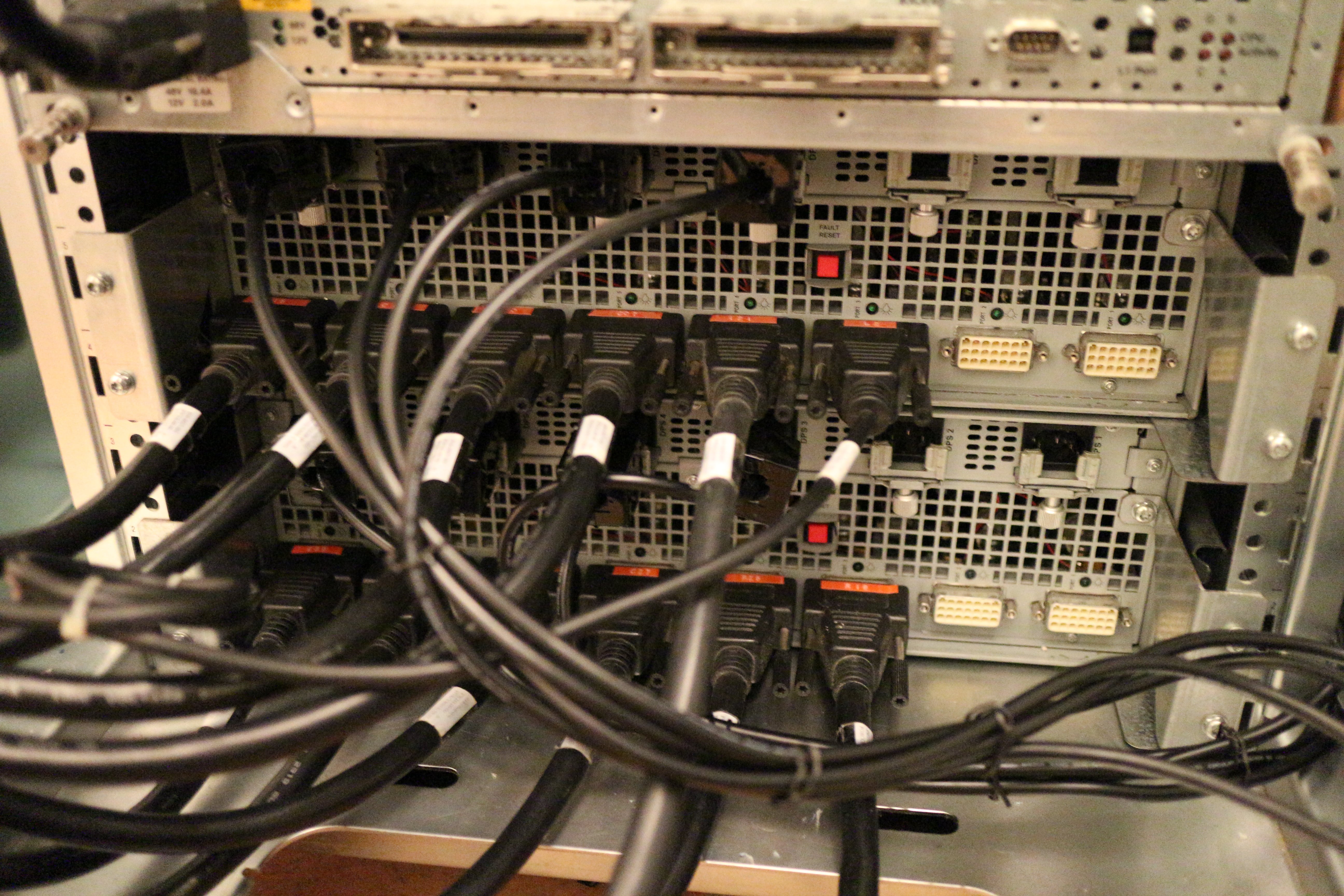
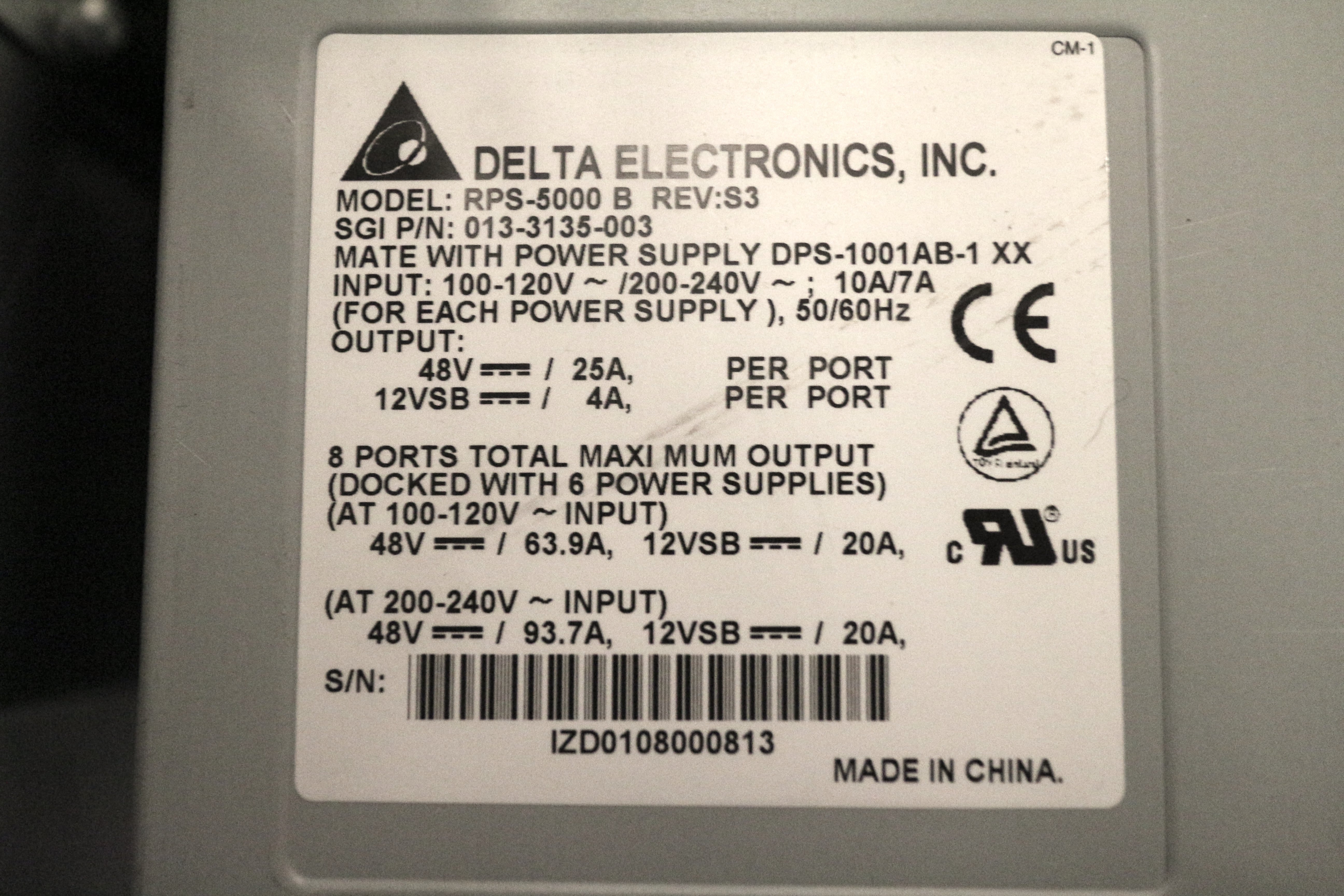
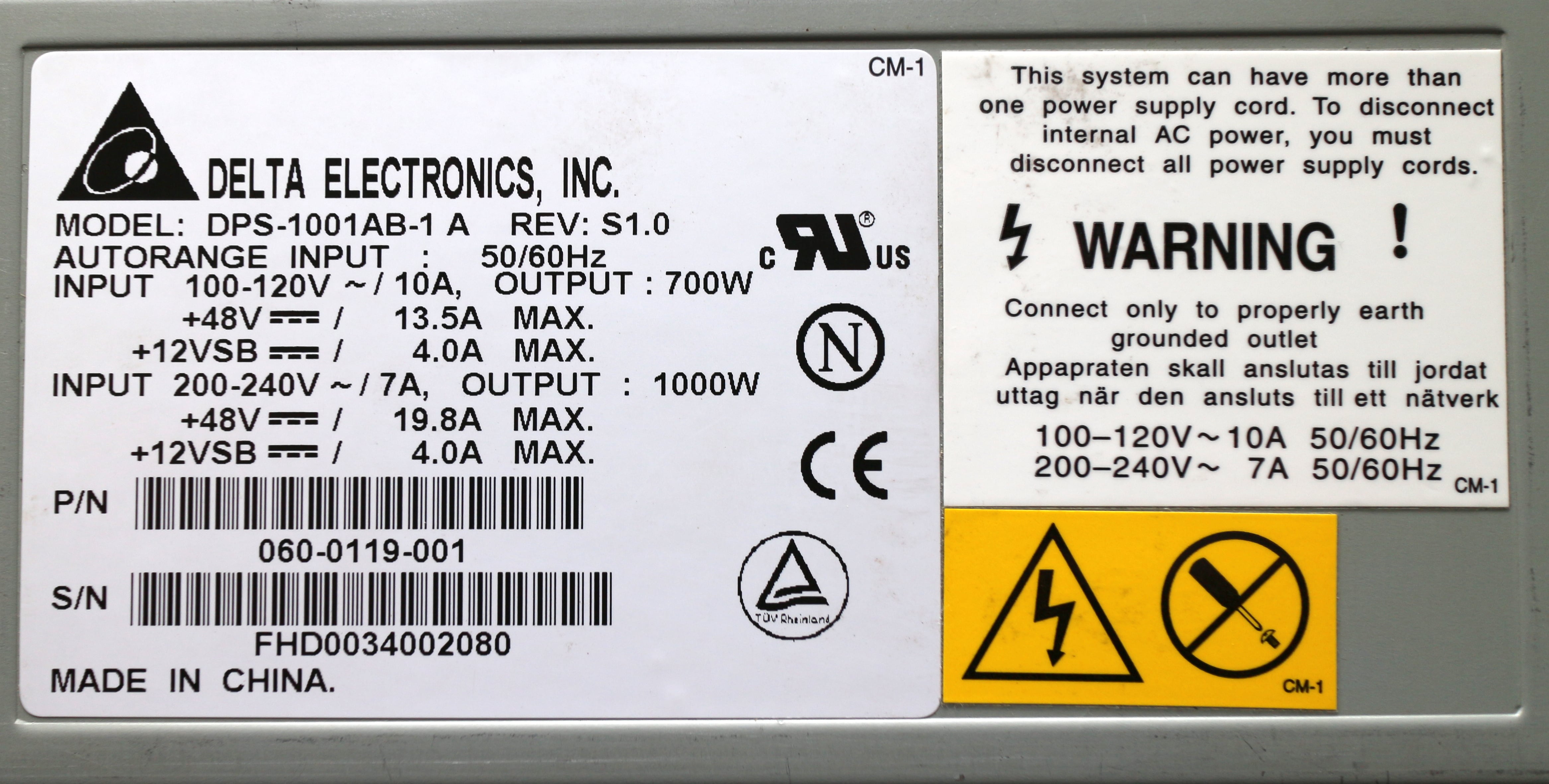
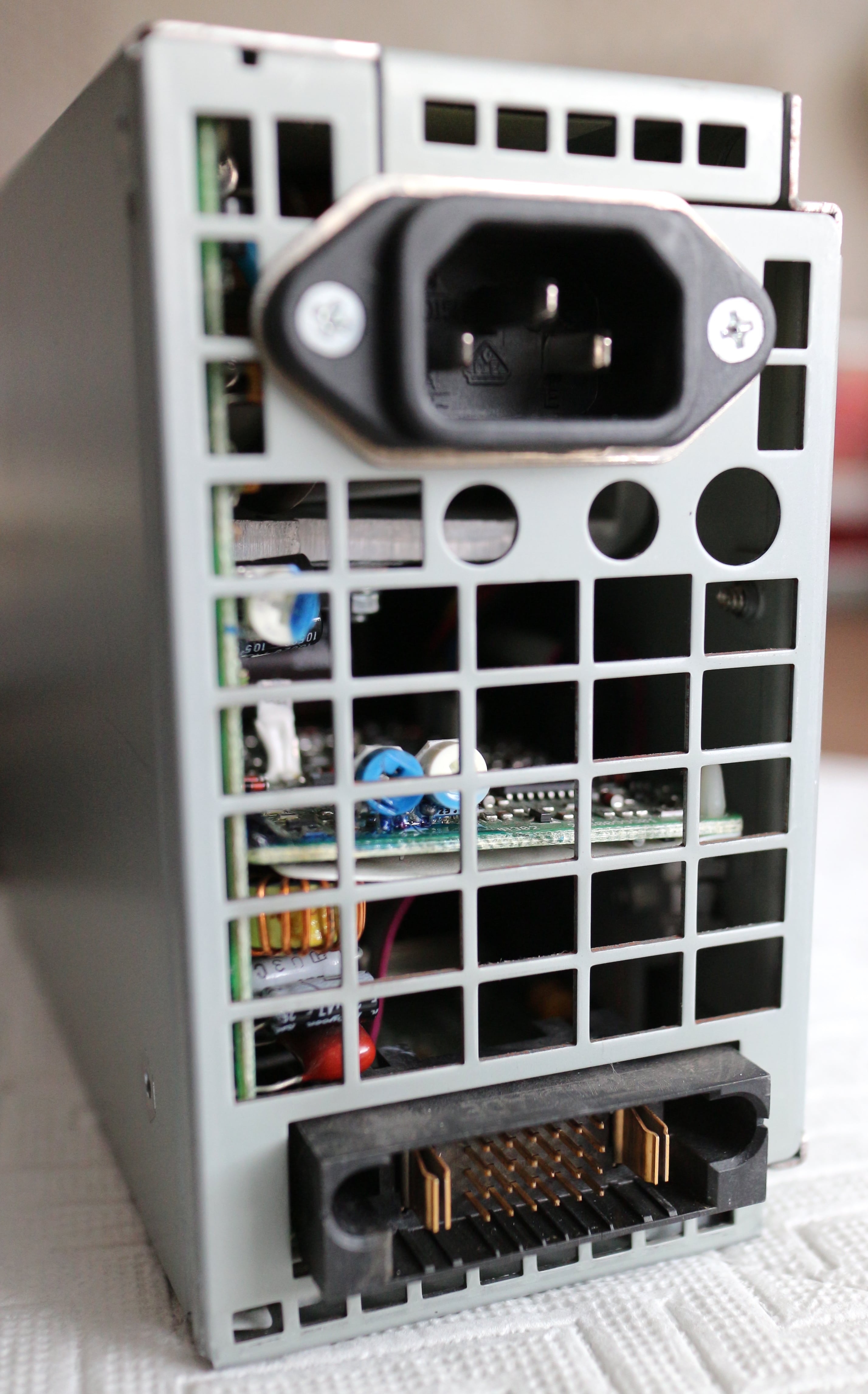
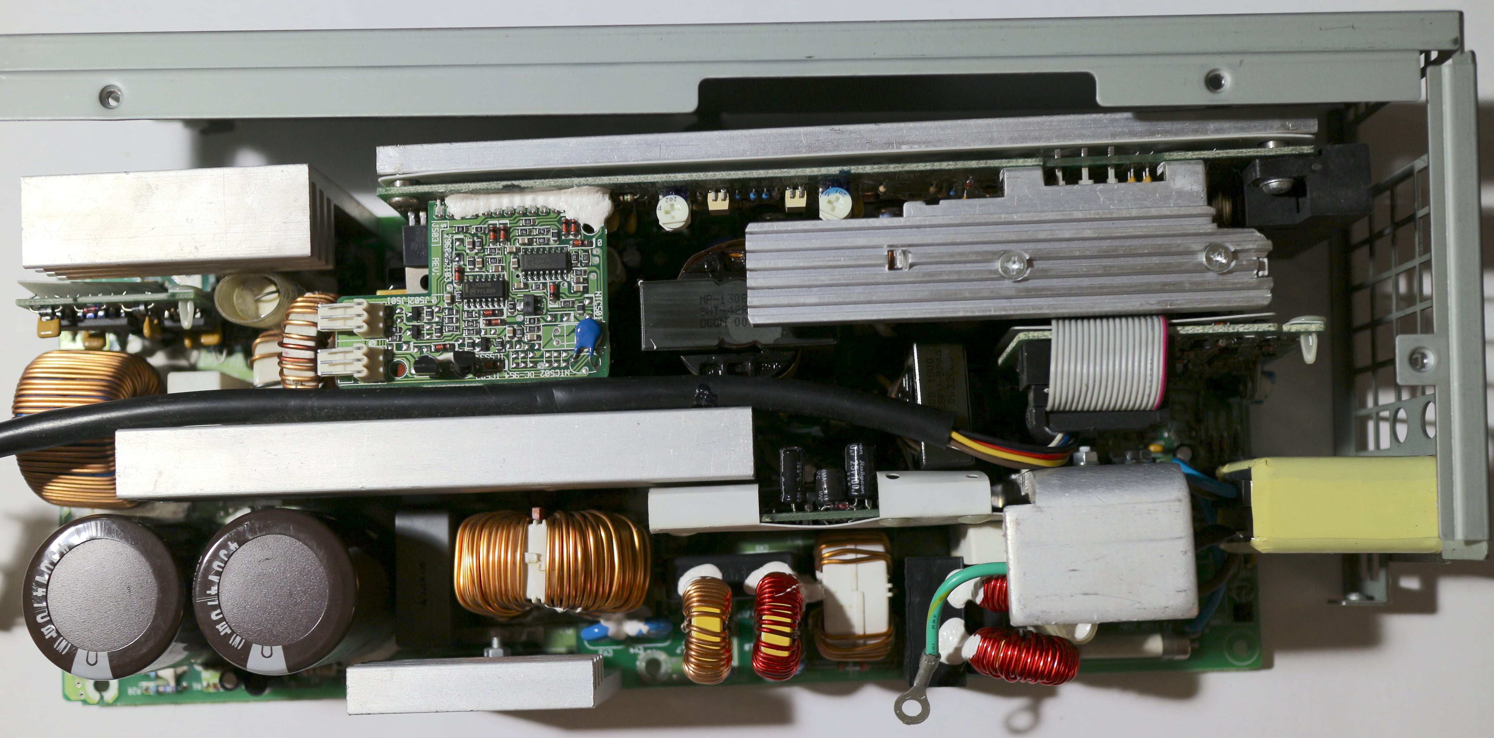
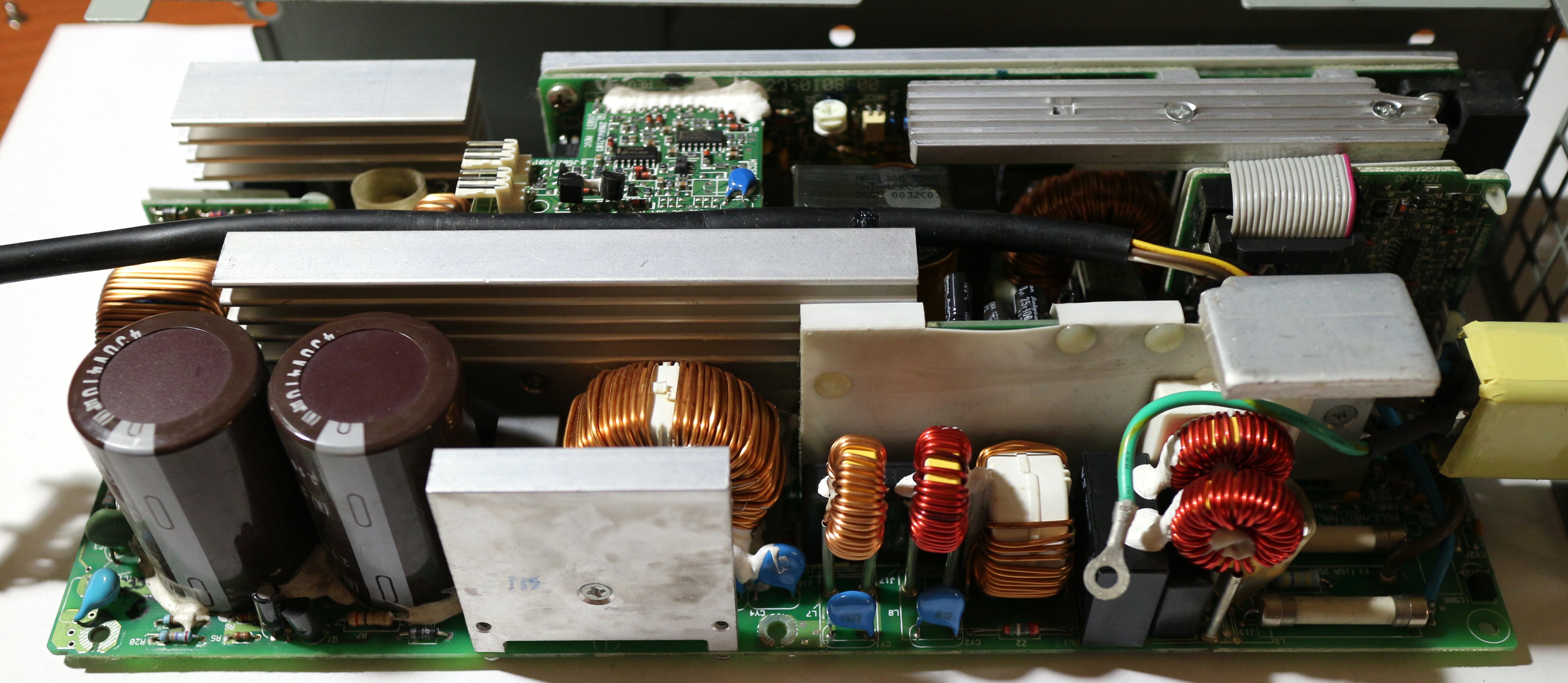
| Power bay |  |  | Provides 48V DC power to bricks within a rack. Contains 3 to 6 power supplies that are hot-swappable and N+1 redundant. |
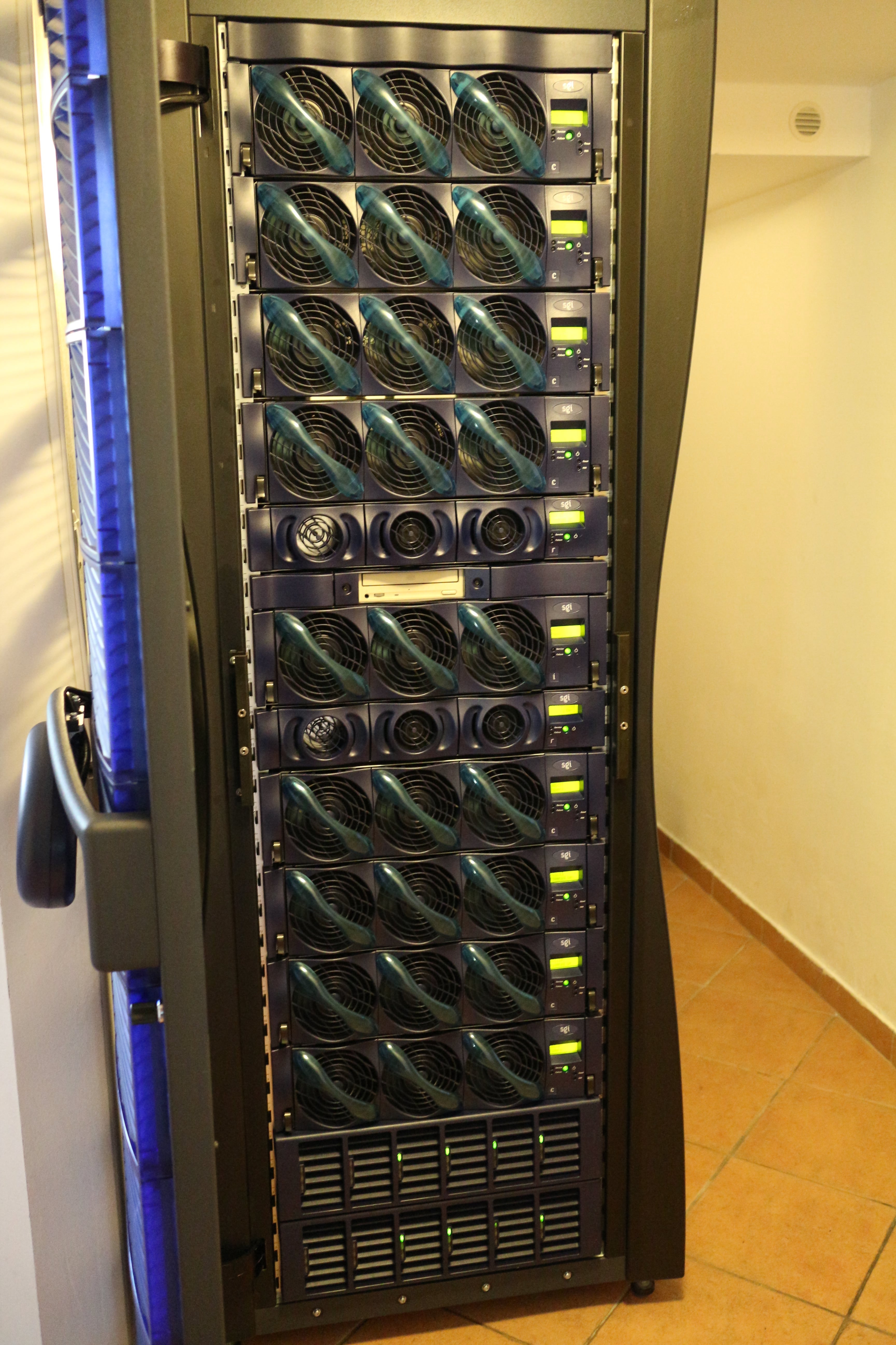
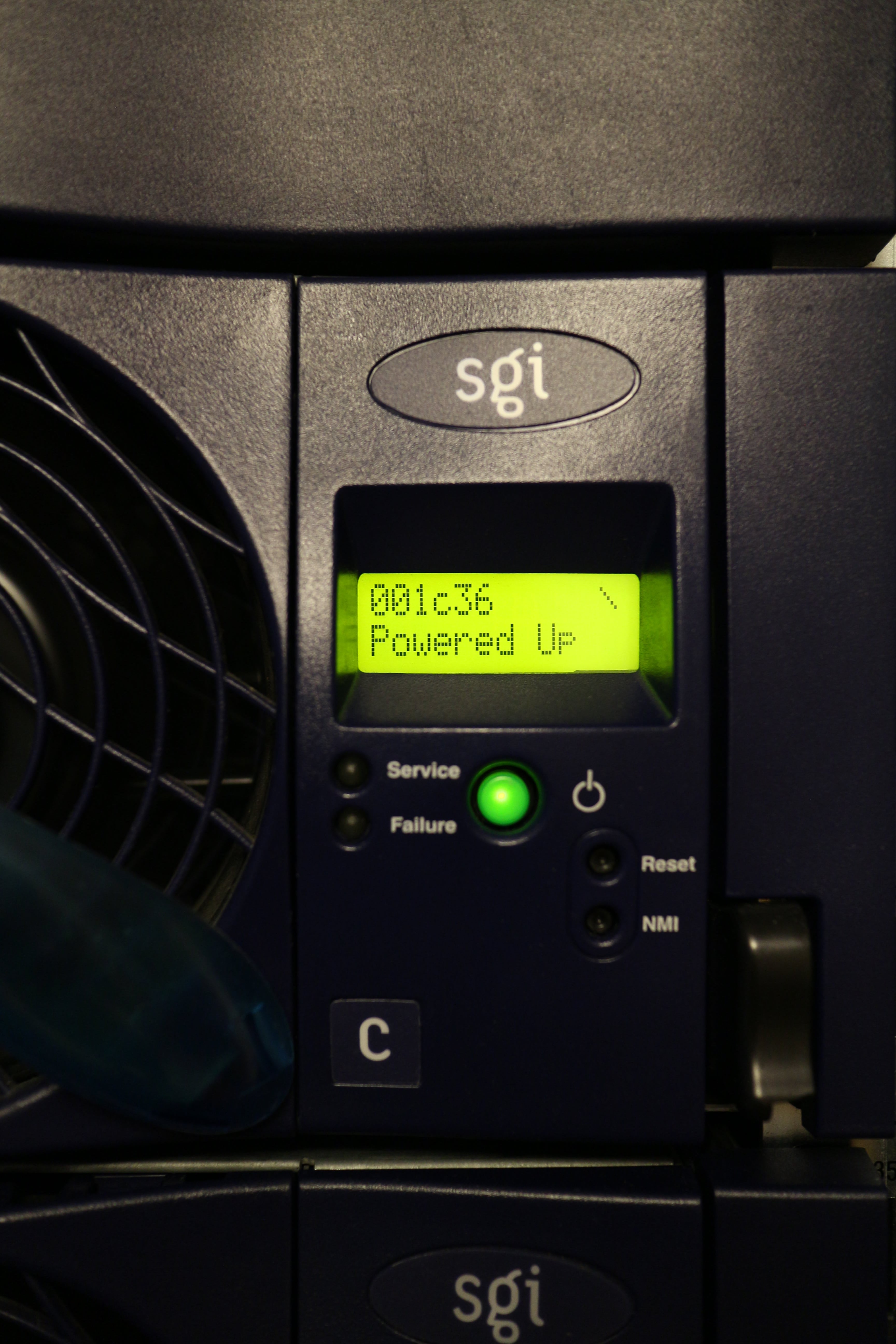
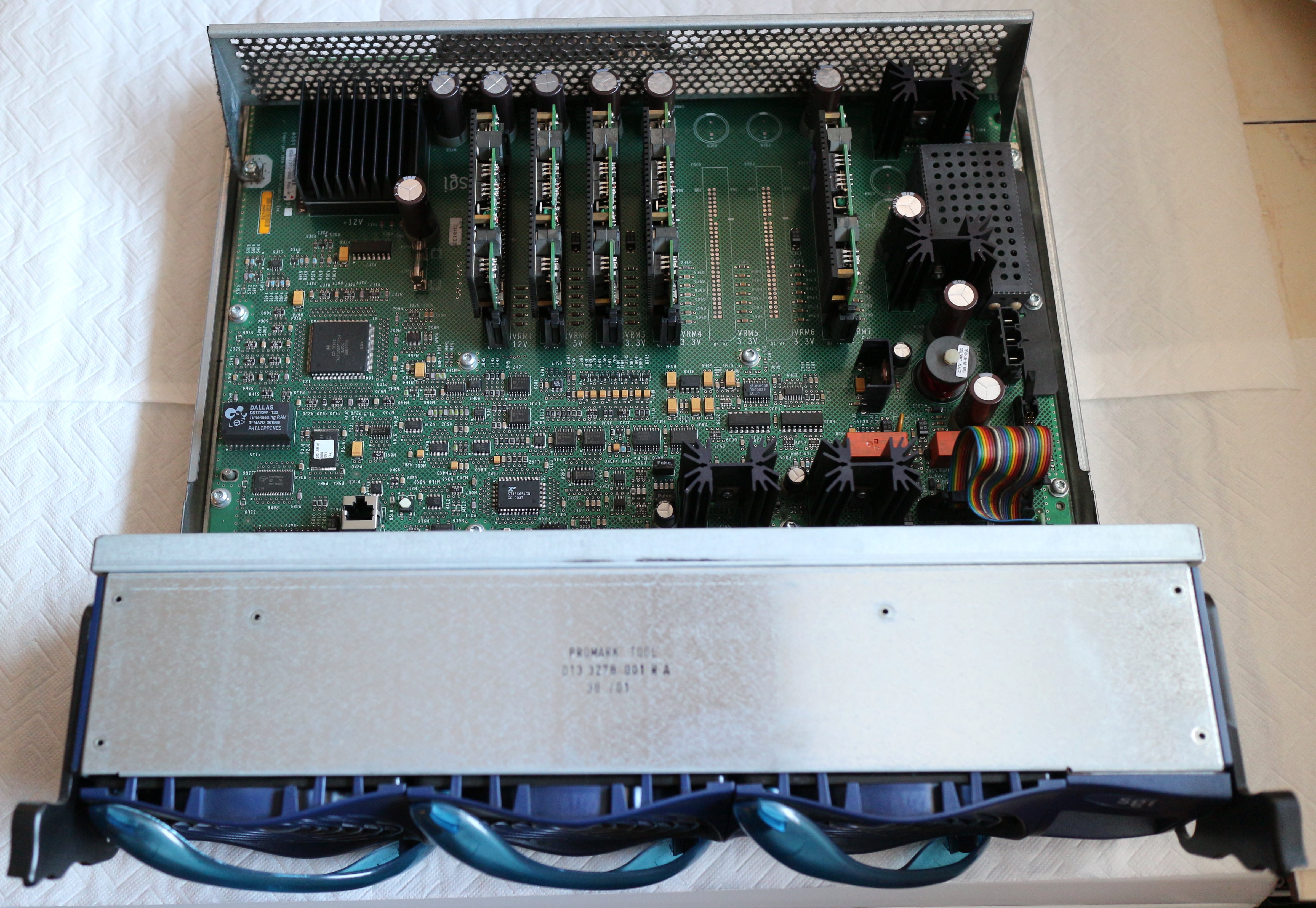
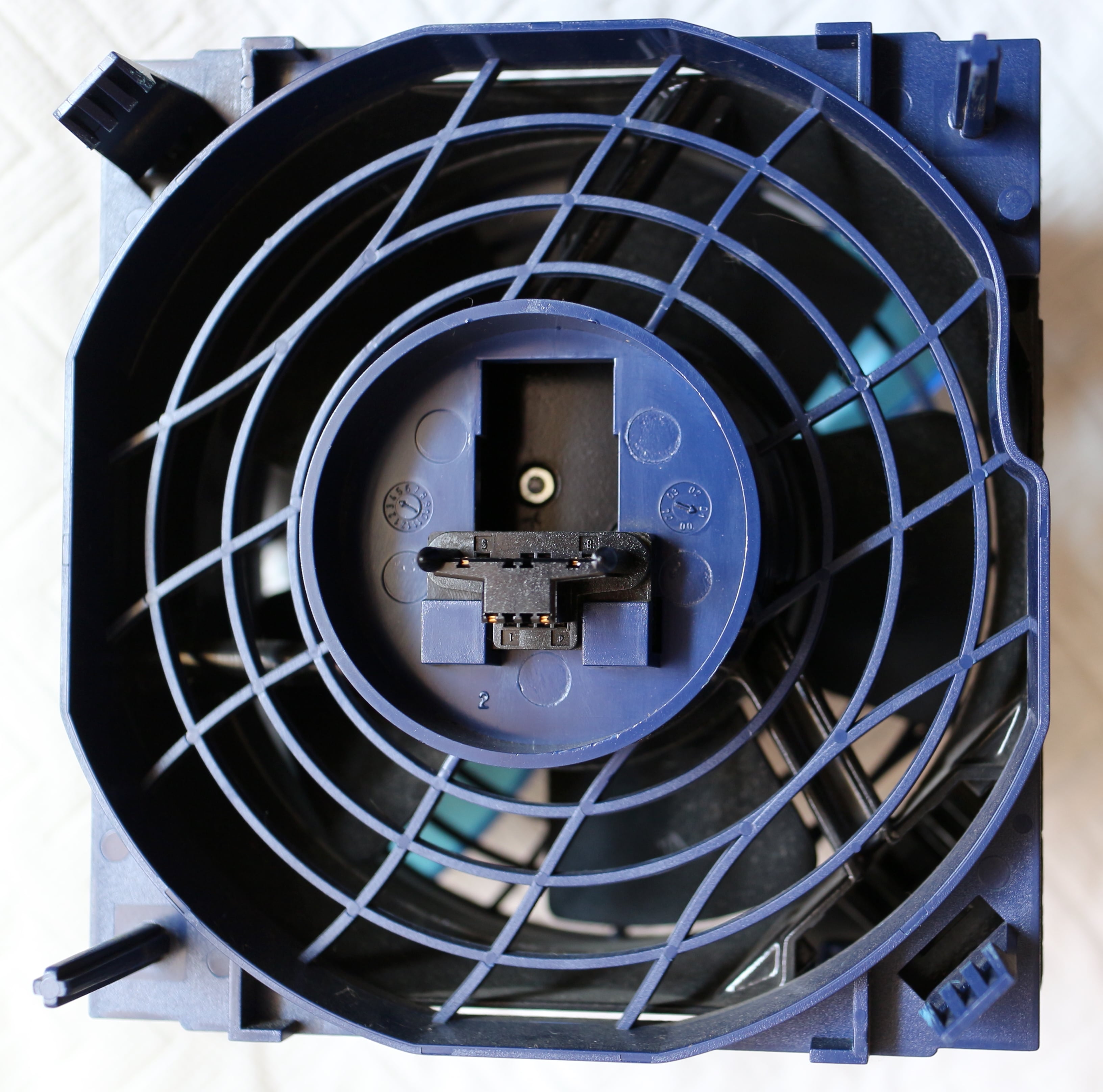
Each brick also contains massive hot-swappable fans in a front-to-back airflow configuration and an L1 controller with an illuminated LCD, showing the status of the brick.
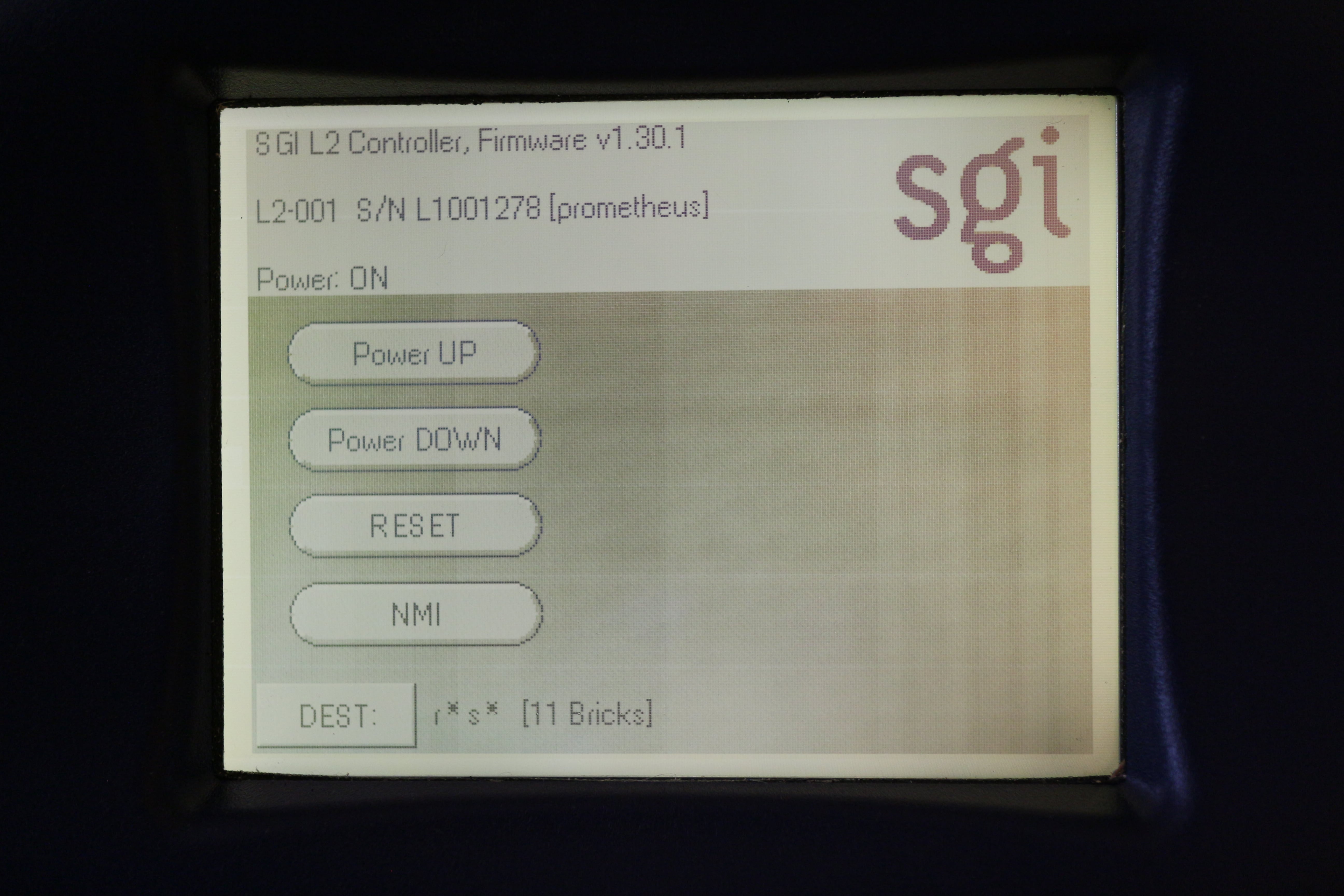
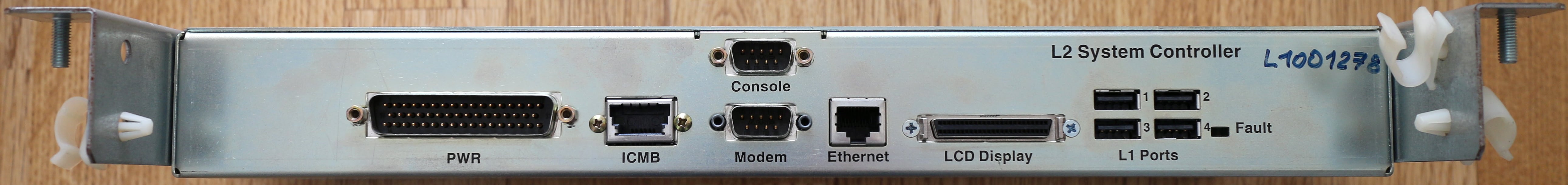
In addition to bricks, each system contains one or more L2 controllers (one per rack) with optional monochrome touchscreen LCD (for turning the system and individual bricks on/off) and power bays (with hot-swappable redundant power supplies). The power supplies provide 48V DC to bricks within a rack.
The difference between the Origin 3200, 3400, and 3800 units is purely in the combination of bricks. The 3200 has a maximum of 8 processors and comes in a short rack with two C-bricks, one I-brick, and one power bay (one slot is free for an additional I-, P-, or X-brick). The 3400 has a maximum of 32 processors and comes in a tall rack with two to eight C-bricks, one I-brick, two R-bricks (6-port), and one power bay. The 3800 series is for larger installations and comes in multiple racks.
Block diagram of the Origin 3400 ↵^
 The above diagram shows a 16-CPU configuration. A 32-CPU configuration contains twice the elements in the diagram and the two routers are linked together with two NUMAlink3 cables.
 Common hardware issues ↵^
The Origin 3000 series machines consist of a lot of parts, so it's not unusual for some of them to start acting up due to old age (but otherwise, it's a very reliable machine).
Replacing batteries ↵^
There are three kinds of batteries in the Origin 3000 machines:
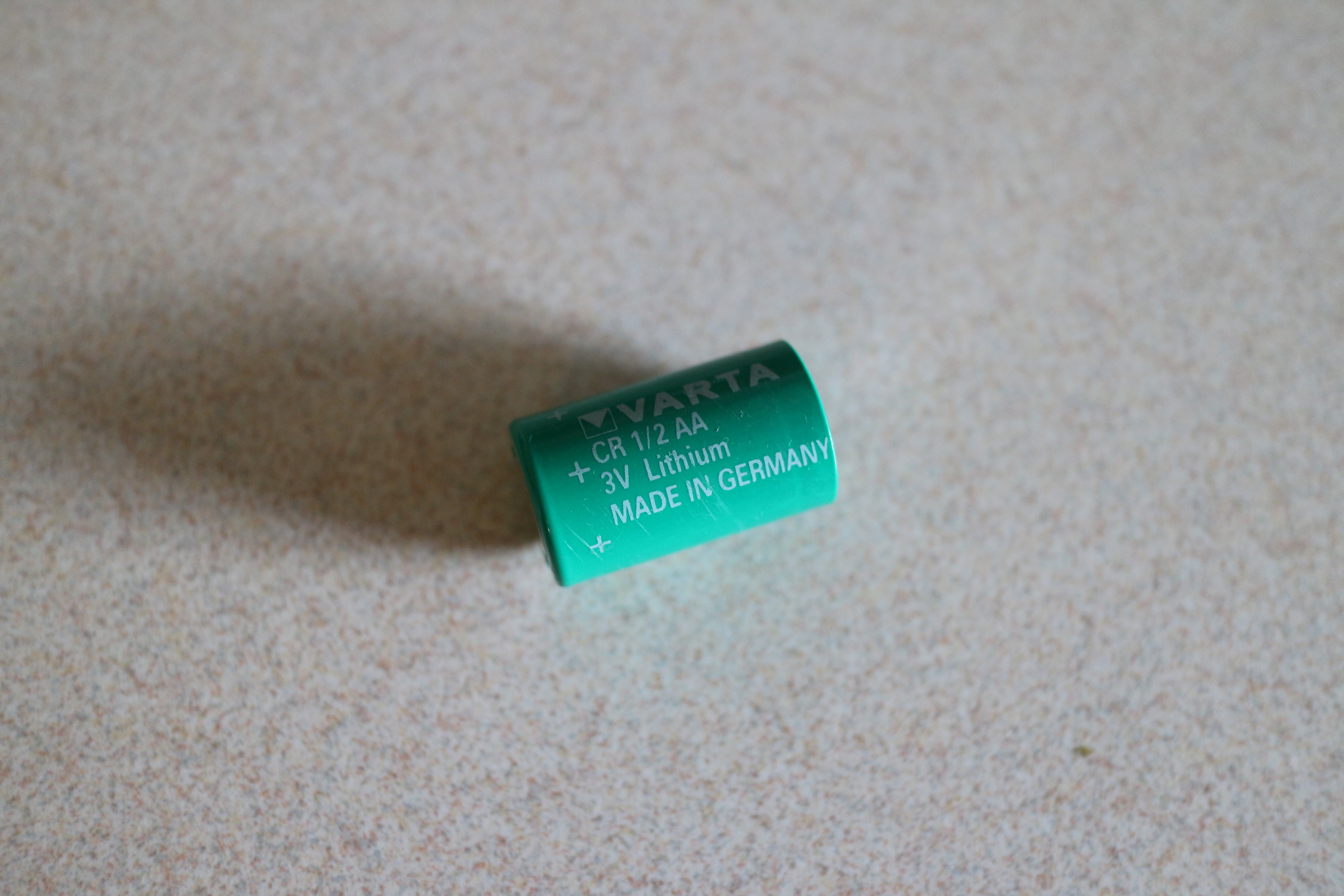
- a CR 1/2AA 3V lithium battery in the L2 controller,
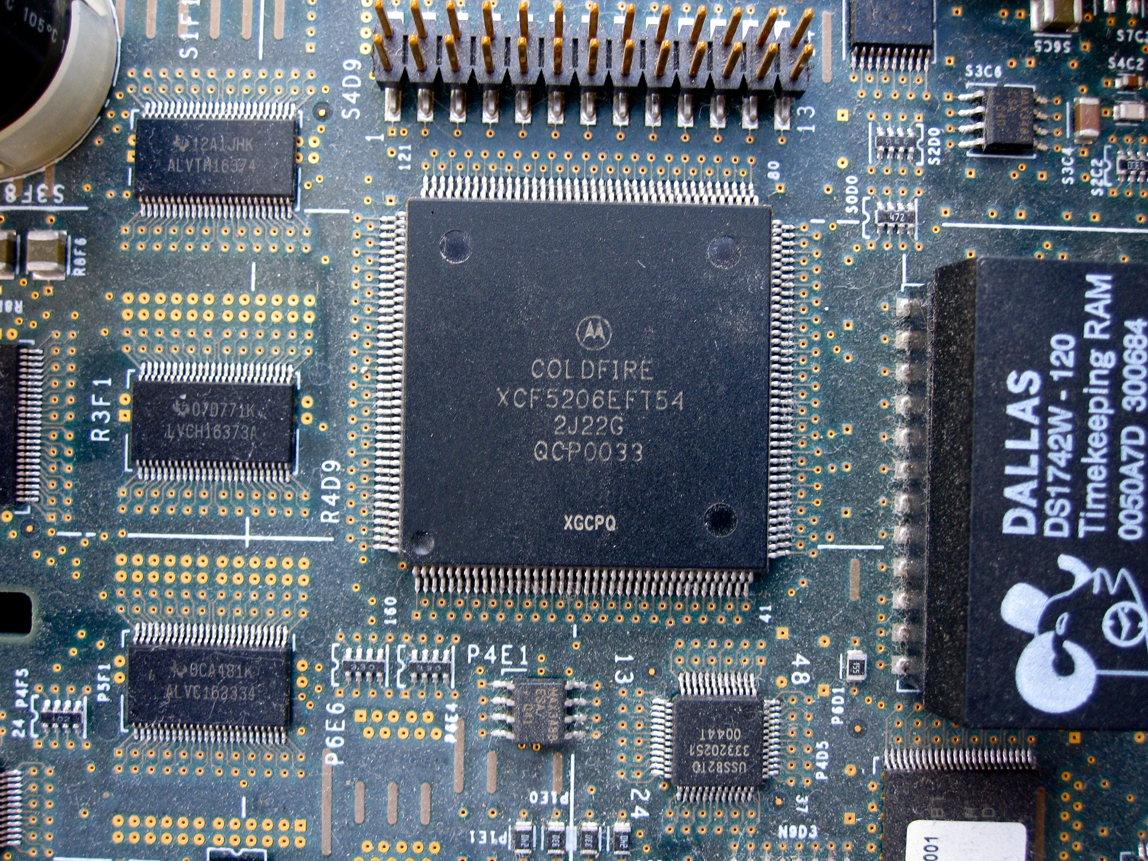
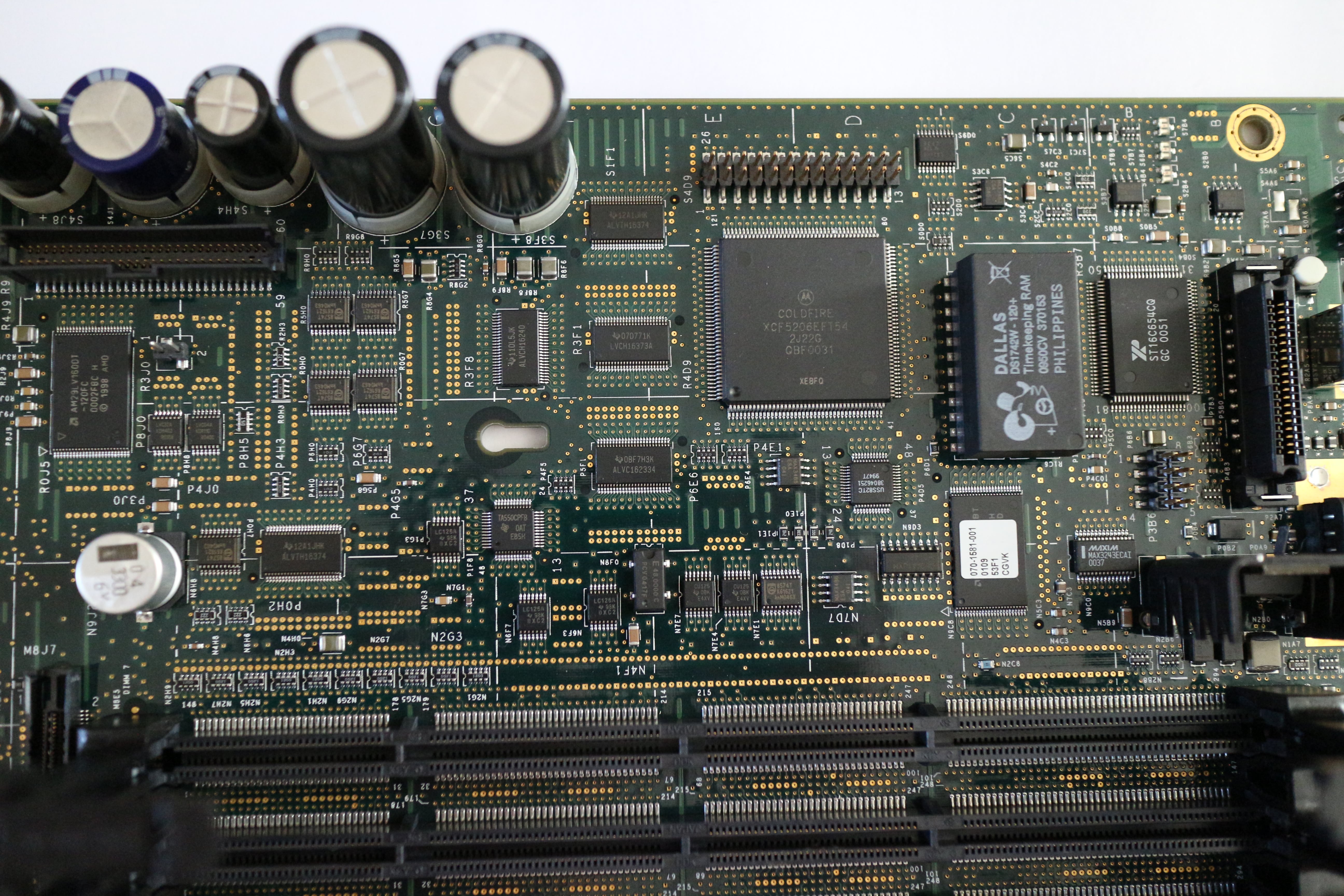
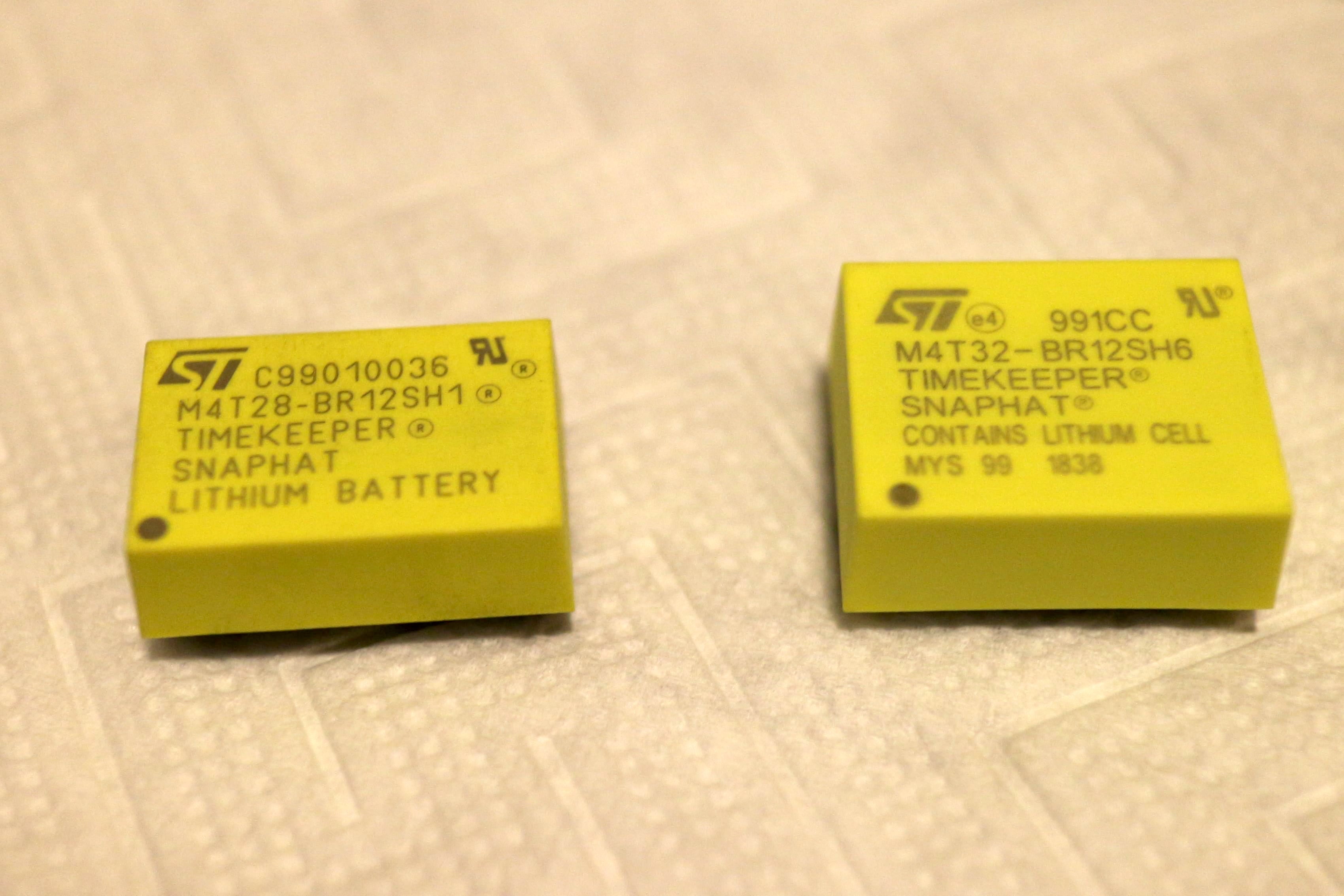
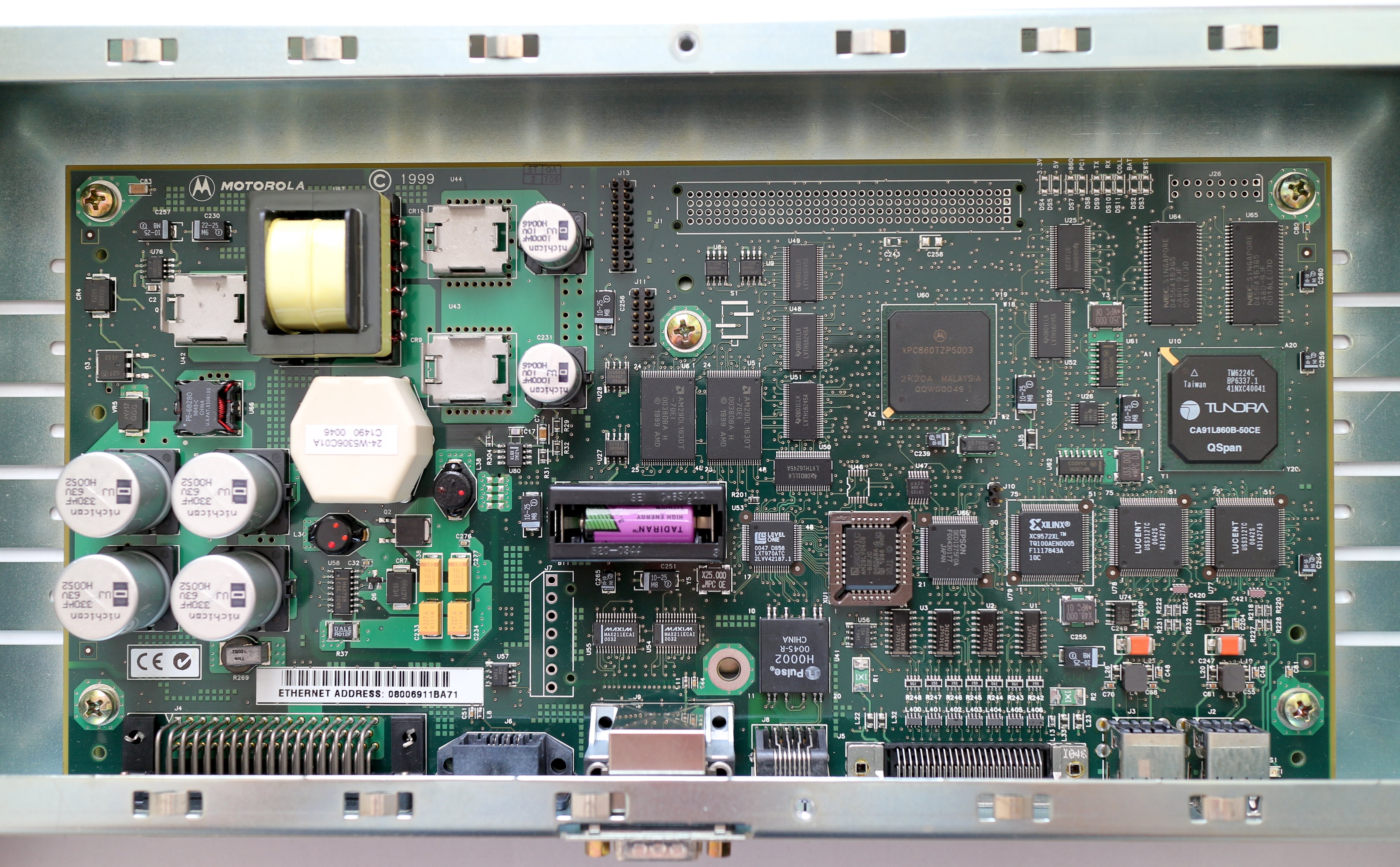
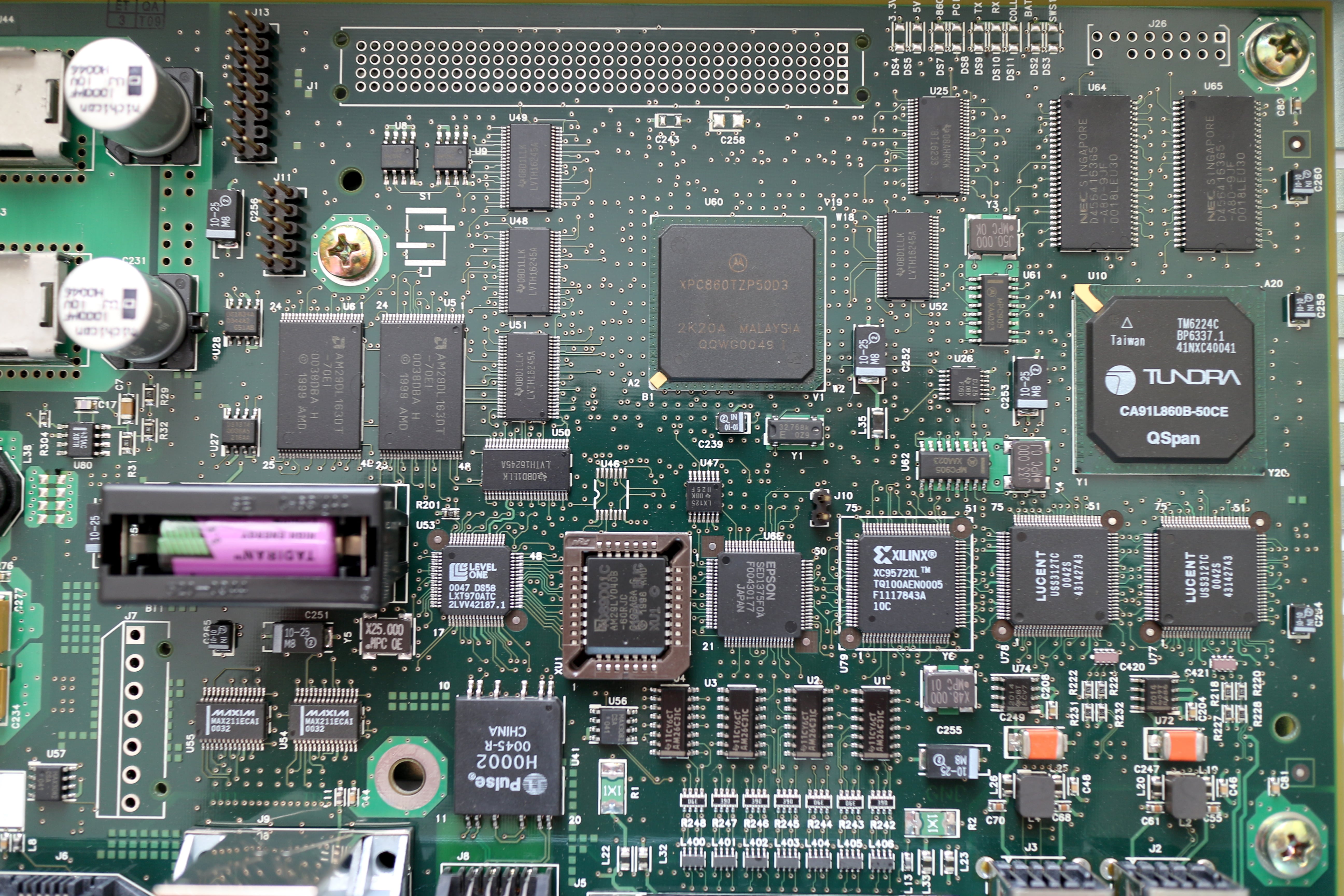
- a yellow ST "snaphat" module (lithium battery + 32.768kHz crystal combo package) in the I-brick,
- a non-replaceable battery in every DS1742W RTC chip inside every brick.
The L2 controller battery can be replaced with any 1/2AA (half-AA) 3V lithium battery, but you can also use the 3.6V batteries more common in older Apple Macs (e.g. Tadiran SL-750/S) — these normally have a higher capacity than the standard 3V batteries, so they last longer. I use a Tadiran SL-750/S 3.6V battery in my L2 controller.
To get to the battery, remove the L2 controller from the rack and unscrew its top cover — the battery is mounted in a holder in the middle of the board.
After replacing the battery, set the current date and time using the "date" L2 command.
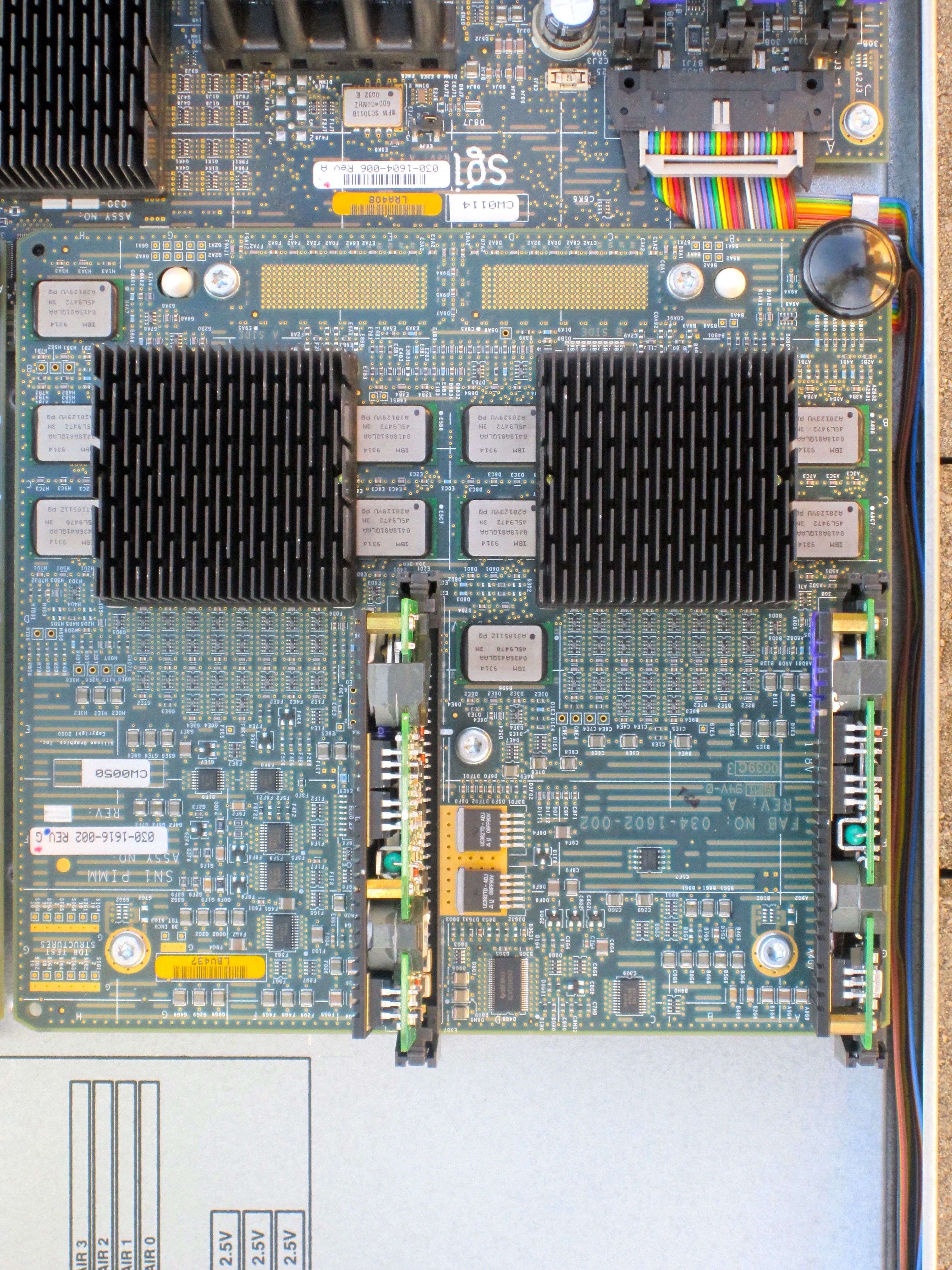
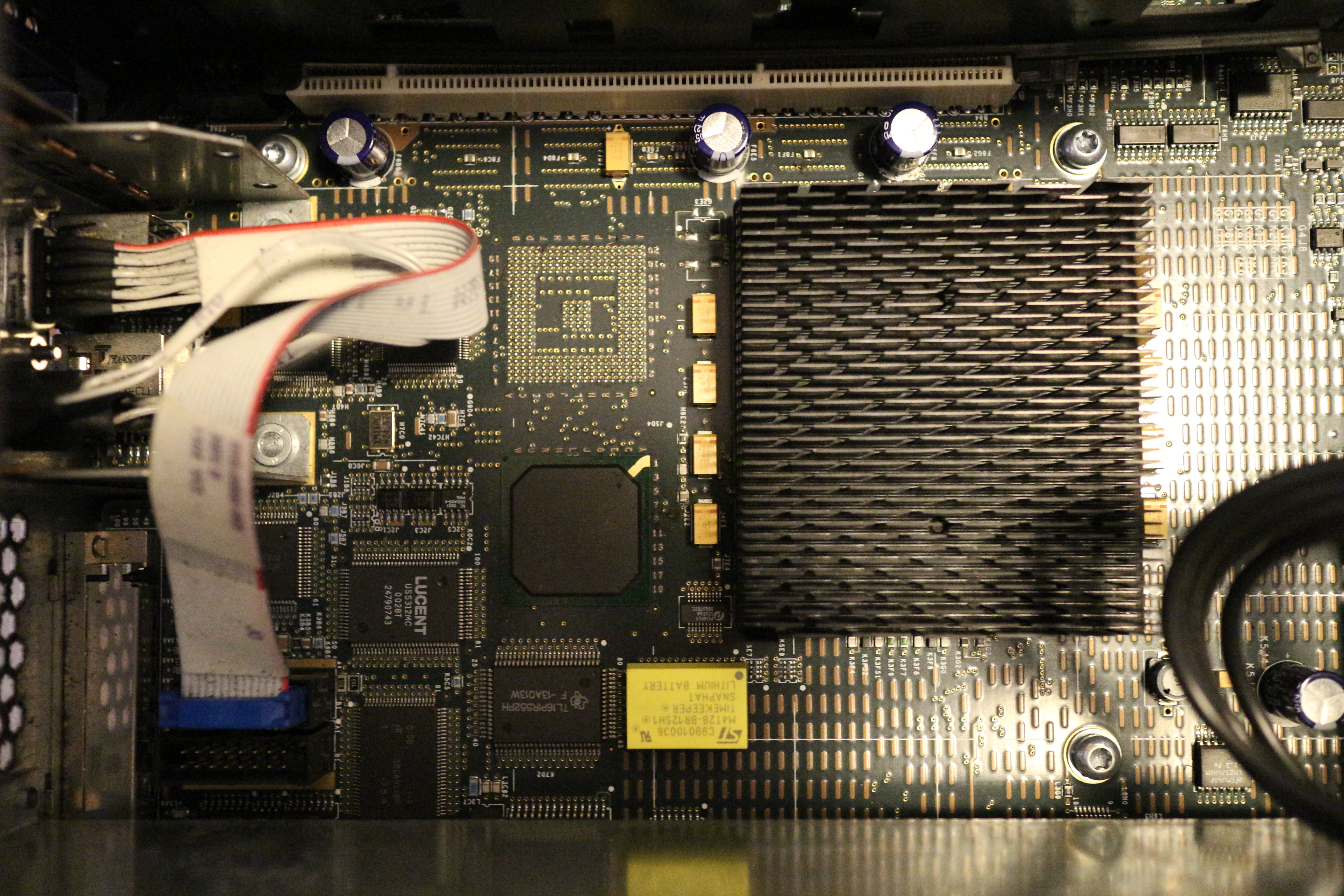
The I-brick battery can be replaced either with the original ST M4T28-BR12SH1 (48 mAh capacity), or even better, with a higher-capacity industrial ST M4T32-BR12SH6 (120 mAh capacity). The last part of the the part number denotes the temperature range — SH1 is commercial (0C to 70C) and SH6 is industrial (-40C to +85C). I use an M4T32-BR12SH6.
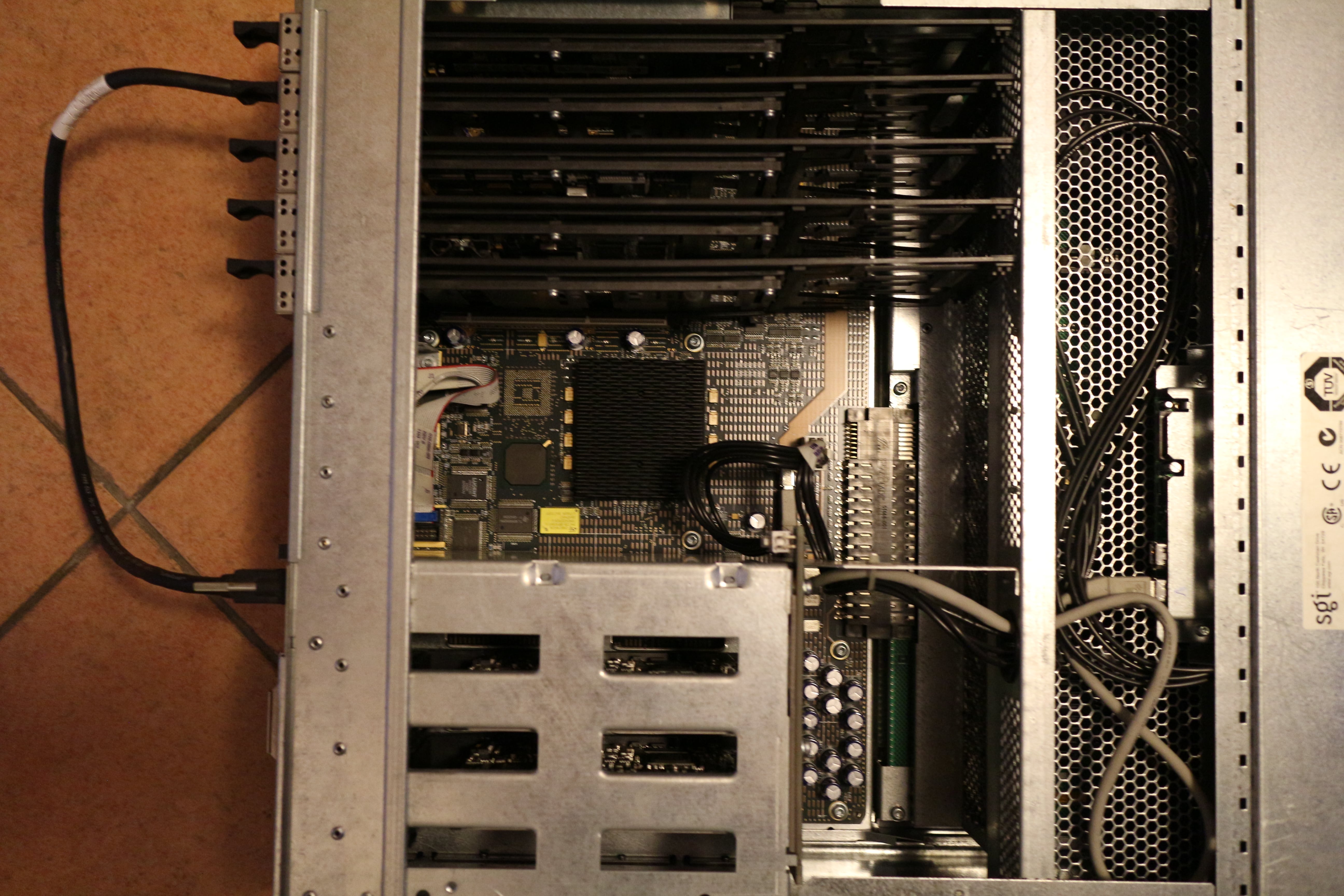
To get to the battery, remove the I-brick from the rack and unscrew the top panel located towards the back of the brick — the battery is located in the middle of the board, near the large black heatsink. Use an IC remover tool to gently remove it from the socket and put the new one in its place (make note of the orientation!).
After replacing the battery, set the current date and time in IRIX.
The non-replaceable batteries inside the DS1742W RTC chips don't really pose any problems for the Origin (unlike in some other systems), in my experience. In the case of R-bricks, having flat batteries is even advantageous, as they will happily accept any serial number, so you can mix and match them with any Origin system you want! (See section R-brick serial number mismatches below for more information.)
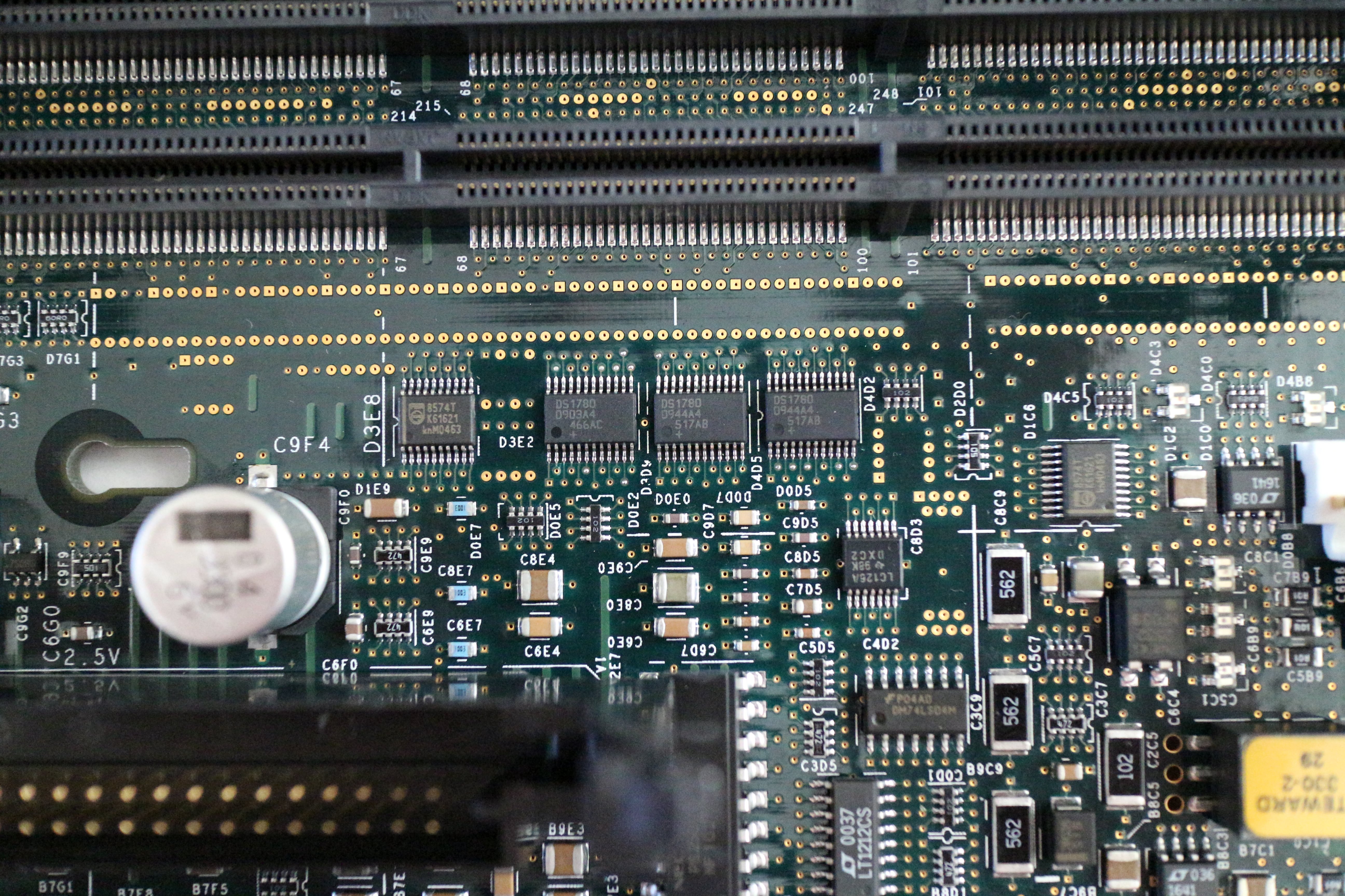
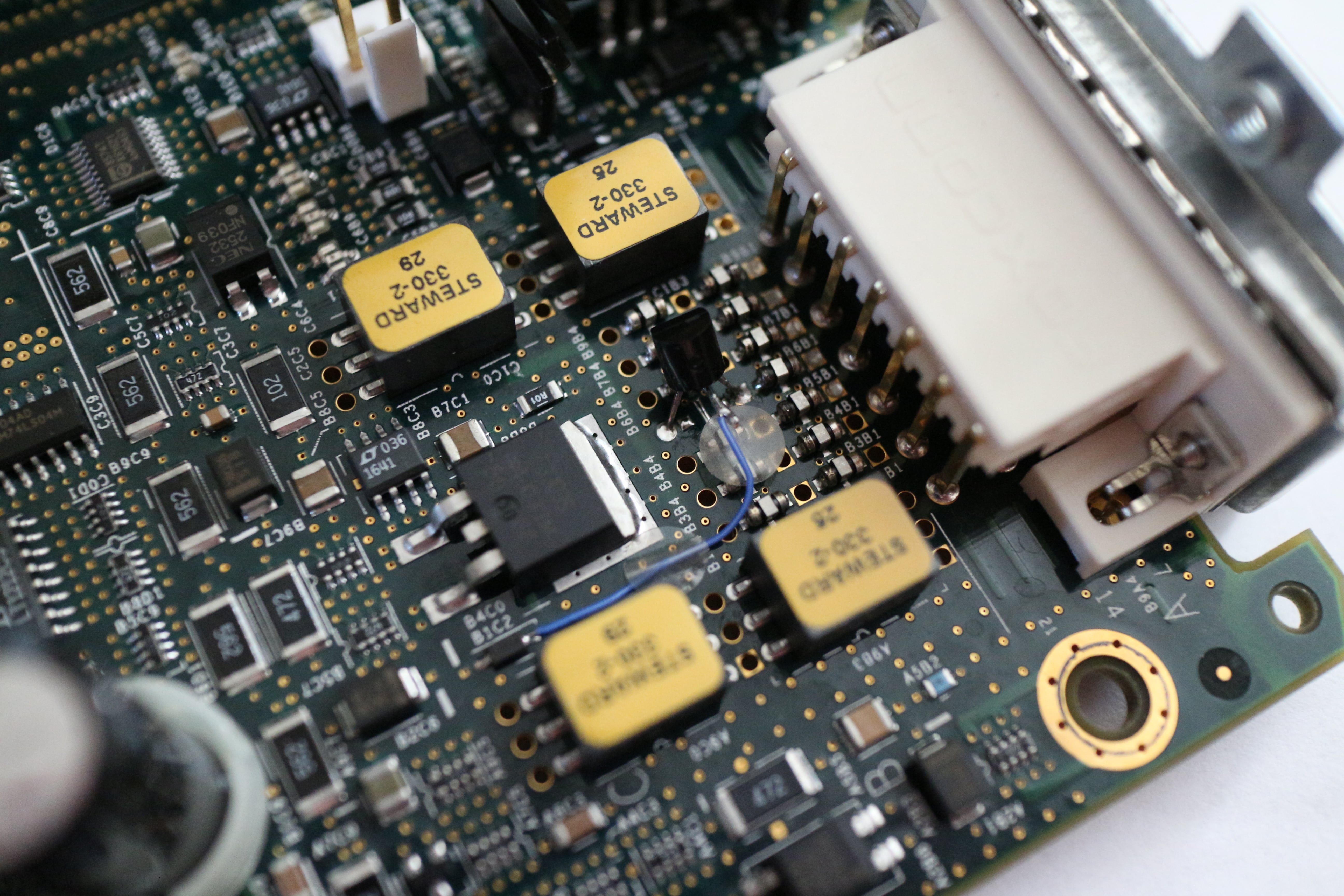
Dealing with faulty DS1780 chips ↵^
SGI got a bad batch of DS1780E monitoring chips that seem to fail over time, resulting in a lot of annoying bogus error messages related to environmental monitoring on all systems based on the Origin 3000 design (Fuel, Tezro, etc.).
Typical error messages on the L2 console include:
001i21 ALERT: Error reading monitor POWER 1 interrupt status 1: no acknowledge
001c07 ALERT: Error reading monitor NODE 0 interrupt status 1: no acknowledge
001c30 ALERT: Error reading monitor NODE 2 interrupt status 1: no acknowledge
001c33 ALERT: Error reading monitor NODE 2 interrupt status 1: no acknowledge
001c33 ALERT: Error reading monitor PIMM1 A interrupt status 1: no acknowledge
001c33 ALERT: Error reading monitor PIMM1 B interrupt status 1: no acknowledge
001r25 ALERT: Error reading monitor POWER interrupt status 1: no acknowledge
And so on (these errors repeat every few seconds). What it's trying to tell you is "I can't talk to the DS1780E chip, it's not responding!"
I haven't had the time to pinpoint the exact nature of the error, but in addition to giving bogus temperature and voltage readings, I suspect that the faulty chips drive the I2C bus lines either high or low at inappropriate times, thus preventing communication from taking place on the bus.
This isn't such a big problem on the Origin, as you can just disable environmental monitoring with "* env off" (and "* env temp off") on the L2 controller (you only need to do this once, the bricks will remember the setting). Then to turn off the nagging messages, do "l1dbg printf off" on the L2 controller (you need to do this every time you apply power to the Origin rack). If you do disable environmental monitoring, make sure you at least manually monitor the temperatures, so the system doesn't overheat.
The proper way to fix this is to replace all the DS1780E ICs with new ones (they're still being made). However, in an Origin, each brick has multiple of these (e.g. a C-brick has three on the motherboard plus two on each PIMM, an I-brick has three on the removable power section), so in a larger system, replacing about 65 surface-mount ICs is an incredibly tedious task.
Nevertheless, I have managed to replace all the faulty DS1780E ICs in my Origin (around 50 of them!) and have re-enabled environmental monitoring ("* env on" and "* env temp on"). I left the working DS1780E ICs alone, as it will be interesting to see if they also develop defects with time or not.
"No L1 comm!" error ↵^
One of the C-bricks in my Origin 3400 used to always report this error on its L1 controller's LCD when I first connected it to power. However, after I toggled the power switch on the back of the affected C-brick, it happily worked as if nothing is wrong!
Initially, I thought that this was a problem with the reset circuitry of the L1 controller, but in fact it's related to the DS1742W RTC module!
If the DS1742W module's battery runs out, its memory can get corrupted, leading to this error. It works after toggling power, because the L1 controller is smart enough to copy the settings from neighboring bricks and/or the L2 controller.
To fix this, simply replace the faulty DS1742W module with a new one. Depending on your configuration, you might need to set the brick's rack/slot manually after doing this, using the L1 command "brick rs 001 10" (for rack 001 slot 10, for example).
"enet_ssram: ssram address walk error" ↵^
This error happens sometimes during boot after powering-on the Origin rack after it has been off for a while. It goes away after doing an "enableall" and "update", then "reset" in the PROM command monitor.
It doesn't appear if the system is put in stand-by mode when not in use instead of turning it completely off or if the system is left to warm-up in stand-by mode for a few hours. Not surprising, as these systems were really meant to be on all the time.
Replacing faulty RAM ↵^
I haven't had a good DIMM go bad on its own yet, but I have bought bad RAM on eBay.
In case of bad RAM, you will get errors such as these during boot:
MAIN MEMORY ERROR AT: Location DIMMs/bank Addr Offset  subtest
(0x9600000080000000)   001c10  2 & 3/ 0   0x00000000   Base + Walk/Inv
	expected: 0xaa55aa55aa55aa55,0xaa55aa55aa55aa55,0xa55a
	  actual: 0xaa55aa55aa55aa55,0x5a55aa55aa55aa55,0xa55a
	    diff: ^x................,^xf...............,^x....

suspect devices = [Dimm 2 : A4B6]
These errors are really useful, since they show you which chip on which DIMM is malfunctioning. If you're so inclined, you can desolder the broken chip and solder-in a replacement. However, the error might not always be directly caused by the given chip — e.g. a damaged decoupling capacitor or a scratched contact on the edge connector (common with DIMMs that were thrown around) can also cause issues that can be misattributed to a chip.
After printing multiple error messages like the one above, the power-on diagnostics will fail with:
DIAG RESULTS:
         /hw/module/001c10/node/mem: MEMBANK(S) 2 3 4 5  disabled
                 Reason:
                         Bank 2: Some DIMMs failed mem test.
                         Bank 3: Some DIMMs failed mem test.
                         Bank 4: Some DIMMs failed mem test.
                         Bank 5: Some DIMMs failed mem test.
In this case, you need to remove the faulty DIMMs, then in the PROM command monitor, do "enableall", then "update", and finally "reset".
If you don't perform these steps, the DIMM slots will remain disabled even if you put good RAM into them!
If you're unlucky and you put the bad RAM into DIMM slots 0 and 1, the system may fail to boot entirely. Put good RAM in the next two banks (2 and 3), do the "enableall+update+reset" steps, move good RAM back to slots 0 and 1, repeat the "enableall+update+reset" steps, and everything should be back to normal.
R-brick serial number mismatches ↵^
The Origin 3000 series router bricks are locked to the serial number of the system they're in. This means that if you move an R-brick to a system with a different serial number, it will refuse to work!
This serial number is stored in the DS1742W battery-backed NVRAM chip inside the R-brick.
The workaround for this is really simple — replace the DS1742W chip with one that has a flat battery, then the R-brick will always copy the serial number from the system it's in!
You can also replace it with a new chip, in which case it will copy the serial number from the system it's in only the first time, then it will remain locked to that serial.
Alternatively, if you have an old-enough L1 controller firmware on the R-brick, you can try the command "let the carnage begin", after which you can issue the command "serial clear", then after rebooting the L1 controller ("reboot_l1"), the R-brick should copy the system's serial from the L2 controller.
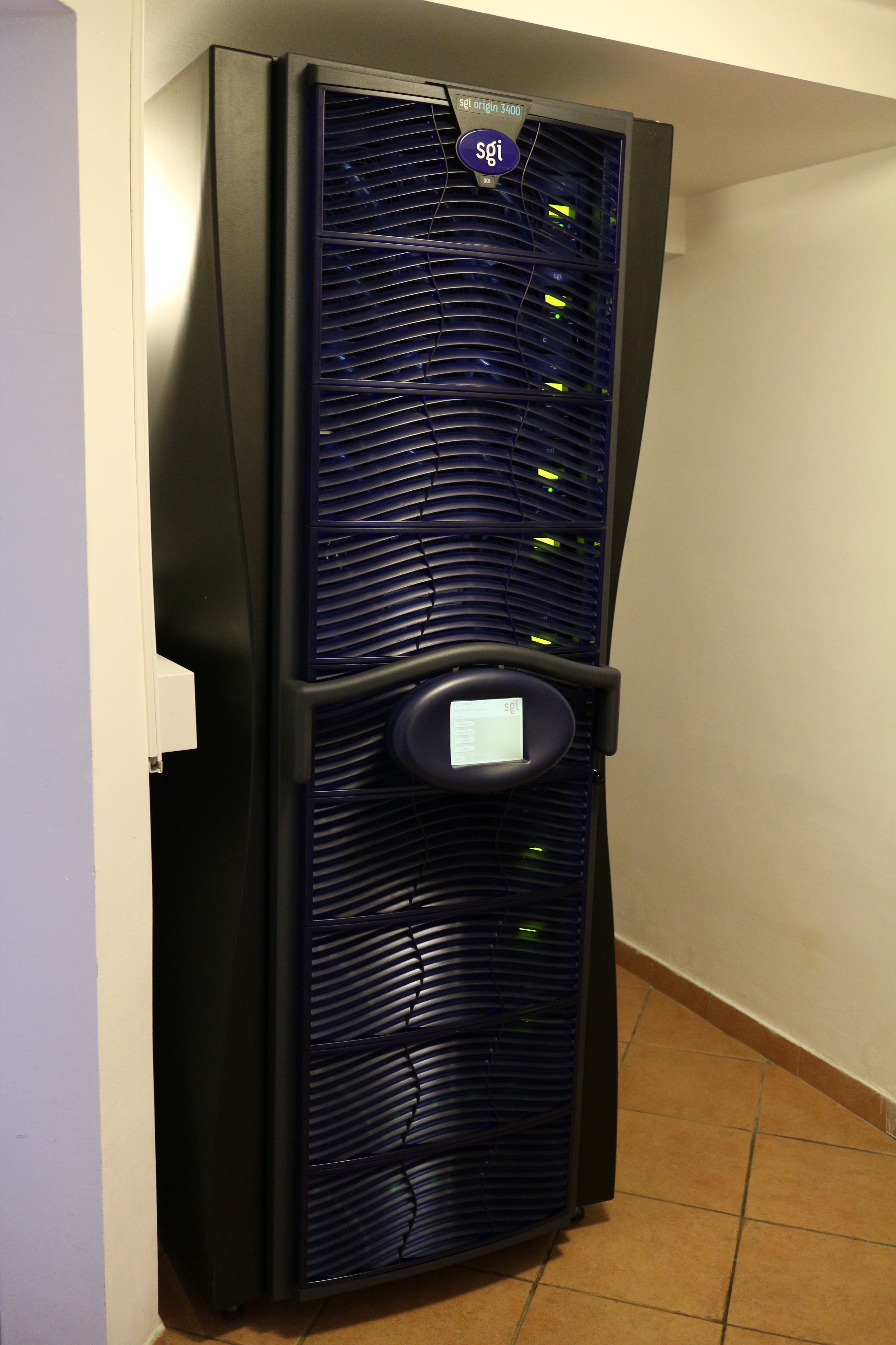
My Origin 3400 ↵^
My Origin 3400 has 32 processors and 32GB of RAM. It consists of eight C-bricks, two R-bricks, and one I-brick. The processors are mixed-speed — 24 of them are 500MHz R14000 and 8 are 400MHz R12000; both types of processors have 8MB of L2 cache. The root filesystem is on two 200GB SLC solid-state fibre-channel drives (Hitachi HUSSL4020ALF400) running in RAID-1 (mirrored) mode.
This system was put together from two separate 16-CPU Origin 3400 machines.
The first machine came from the UK, without the rack, as it was too heavy to ship — it weighed about 230kg (200kg for the bricks, the rest of the weight were cables). Power consumption for a 16-processor Origin 3400 is about 1320W when idle, about 1400W at full load, and 300W in stand-by mode (system off, but L1 and L2 controllers on). The power factor is an almost-perfect 0.99!
The second machine came from Croatia (thanks Harold!), where it was used at a large pharmaceutical company until it was decommissioned in 2013. This one came with the full rack and was in very nice condition!
Because of the modular nature of the Origin 3000 series, it was possible to merge the two 16-processor machines into a single 32-processor machine — I simply moved my old bricks into the shiny new rack and connected them together. I have no idea how much the final machine weighs, but it must be at least 500kg if not more (the rack is heavier than it looks, even when empty).
The power consumption of the 32-processor machine is around 2330W when idle, around 2400W at full load, and 450W in stand-by mode (system off, but L1 and L2 controllers on). The power factor when the system is on is a respectable 0.96, and a still-good 0.83 in stand-by mode.
Output of hinv
Processor 0: 500 MHZ IP35
CPU: MIPS R14000 Processor Chip Revision: 1.4
FPU: MIPS R14010 Floating Point Chip Revision: 1.4
Processor 1: 500 MHZ IP35
CPU: MIPS R14000 Processor Chip Revision: 1.4
FPU: MIPS R14010 Floating Point Chip Revision: 1.4
Processor 2: 500 MHZ IP35
CPU: MIPS R14000 Processor Chip Revision: 1.4
FPU: MIPS R14010 Floating Point Chip Revision: 1.4
Processor 3: 500 MHZ IP35
CPU: MIPS R14000 Processor Chip Revision: 1.4
FPU: MIPS R14010 Floating Point Chip Revision: 1.4
Processor 4: 500 MHZ IP35
CPU: MIPS R14000 Processor Chip Revision: 1.4
FPU: MIPS R14010 Floating Point Chip Revision: 1.4
Processor 5: 500 MHZ IP35
CPU: MIPS R14000 Processor Chip Revision: 1.4
FPU: MIPS R14010 Floating Point Chip Revision: 1.4
Processor 6: 500 MHZ IP35
CPU: MIPS R14000 Processor Chip Revision: 1.4
FPU: MIPS R14010 Floating Point Chip Revision: 1.4
Processor 7: 500 MHZ IP35
CPU: MIPS R14000 Processor Chip Revision: 1.4
FPU: MIPS R14010 Floating Point Chip Revision: 1.4
Processor 8: 500 MHZ IP35
CPU: MIPS R14000 Processor Chip Revision: 1.4
FPU: MIPS R14010 Floating Point Chip Revision: 1.4
Processor 9: 500 MHZ IP35
CPU: MIPS R14000 Processor Chip Revision: 1.4
FPU: MIPS R14010 Floating Point Chip Revision: 1.4
Processor 10: 500 MHZ IP35
CPU: MIPS R14000 Processor Chip Revision: 1.4
FPU: MIPS R14010 Floating Point Chip Revision: 1.4
Processor 11: 500 MHZ IP35
CPU: MIPS R14000 Processor Chip Revision: 1.4
FPU: MIPS R14010 Floating Point Chip Revision: 1.4
Processor 12: 500 MHZ IP35
CPU: MIPS R14000 Processor Chip Revision: 1.4
FPU: MIPS R14010 Floating Point Chip Revision: 1.4
Processor 13: 500 MHZ IP35
CPU: MIPS R14000 Processor Chip Revision: 1.4
FPU: MIPS R14010 Floating Point Chip Revision: 1.4
Processor 14: 500 MHZ IP35
CPU: MIPS R14000 Processor Chip Revision: 1.4
FPU: MIPS R14010 Floating Point Chip Revision: 1.4
Processor 15: 500 MHZ IP35
CPU: MIPS R14000 Processor Chip Revision: 1.4
FPU: MIPS R14010 Floating Point Chip Revision: 1.4
Processor 16: 500 MHZ IP35
CPU: MIPS R14000 Processor Chip Revision: 1.4
FPU: MIPS R14010 Floating Point Chip Revision: 1.4
Processor 17: 500 MHZ IP35
CPU: MIPS R14000 Processor Chip Revision: 1.4
FPU: MIPS R14010 Floating Point Chip Revision: 1.4
Processor 18: 500 MHZ IP35
CPU: MIPS R14000 Processor Chip Revision: 1.4
FPU: MIPS R14010 Floating Point Chip Revision: 1.4
Processor 19: 500 MHZ IP35
CPU: MIPS R14000 Processor Chip Revision: 1.4
FPU: MIPS R14010 Floating Point Chip Revision: 1.4
Processor 20: 500 MHZ IP35
CPU: MIPS R14000 Processor Chip Revision: 1.4
FPU: MIPS R14010 Floating Point Chip Revision: 1.4
Processor 21: 500 MHZ IP35
CPU: MIPS R14000 Processor Chip Revision: 1.4
FPU: MIPS R14010 Floating Point Chip Revision: 1.4
Processor 22: 500 MHZ IP35
CPU: MIPS R14000 Processor Chip Revision: 1.4
FPU: MIPS R14010 Floating Point Chip Revision: 1.4
Processor 23: 500 MHZ IP35
CPU: MIPS R14000 Processor Chip Revision: 1.4
FPU: MIPS R14010 Floating Point Chip Revision: 1.4
Processor 24: 400 MHZ IP35
CPU: MIPS R12000 Processor Chip Revision: 3.5
FPU: MIPS R12010 Floating Point Chip Revision: 3.5
Processor 25: 400 MHZ IP35
CPU: MIPS R12000 Processor Chip Revision: 3.5
FPU: MIPS R12010 Floating Point Chip Revision: 3.5
Processor 26: 400 MHZ IP35
CPU: MIPS R12000 Processor Chip Revision: 3.5
FPU: MIPS R12010 Floating Point Chip Revision: 3.5
Processor 27: 400 MHZ IP35
CPU: MIPS R12000 Processor Chip Revision: 3.5
FPU: MIPS R12010 Floating Point Chip Revision: 3.5
Processor 28: 400 MHZ IP35
CPU: MIPS R12000 Processor Chip Revision: 3.5
FPU: MIPS R12010 Floating Point Chip Revision: 3.5
Processor 29: 400 MHZ IP35
CPU: MIPS R12000 Processor Chip Revision: 3.5
FPU: MIPS R12010 Floating Point Chip Revision: 3.5
Processor 30: 400 MHZ IP35
CPU: MIPS R12000 Processor Chip Revision: 3.5
FPU: MIPS R12010 Floating Point Chip Revision: 3.5
Processor 31: 400 MHZ IP35
CPU: MIPS R12000 Processor Chip Revision: 3.5
FPU: MIPS R12010 Floating Point Chip Revision: 3.5
Main memory size: 32768 Mbytes
Instruction cache size: 32 Kbytes
Data cache size: 32 Kbytes
Secondary unified instruction/data cache size: 8 Mbytes
Integral SCSI controller 4: Version SAS/SATA LS1068
  Disk drive: unit 4 on SCSI controller 4
Integral SCSI controller 0: Version Fibre Channel QL2200A
  Disk drive: unit 1 on SCSI controller 0
  Disk drive: unit 2 on SCSI controller 0
Integral SCSI controller 5: Version IEEE1394 SBP2
  IEEE1394 CDROM: node 1010031001c252 port 0 on SCSI controller 5
IOC3/IOC4 serial port: tty4
IOC3/IOC4 serial port: tty5
IOC3/IOC4 serial port: tty3
Gigabit Ethernet: eg0, module 001c07, pci_bus 2, pci_slot 1, firmware version 12.4.10
Integral Fast Ethernet: ef0, version 1, module 001c07, pci 4
IOC3/IOC4 external interrupts: 1
IEEE 1394 High performance serial bus controller 0: Type: OHCI, Version 0 0
USB controller: type OHCI
Output of scsimon
/dev/scsi/sc0d1l0: [HITACHI HUSSL402 CLAR200C165]       19C/66F [0C/32F]
/dev/scsi/sc0d2l0: [HITACHI HUSSL402 CLAR200C165]       19C/66F [0C/32F]
Pictures ↵^

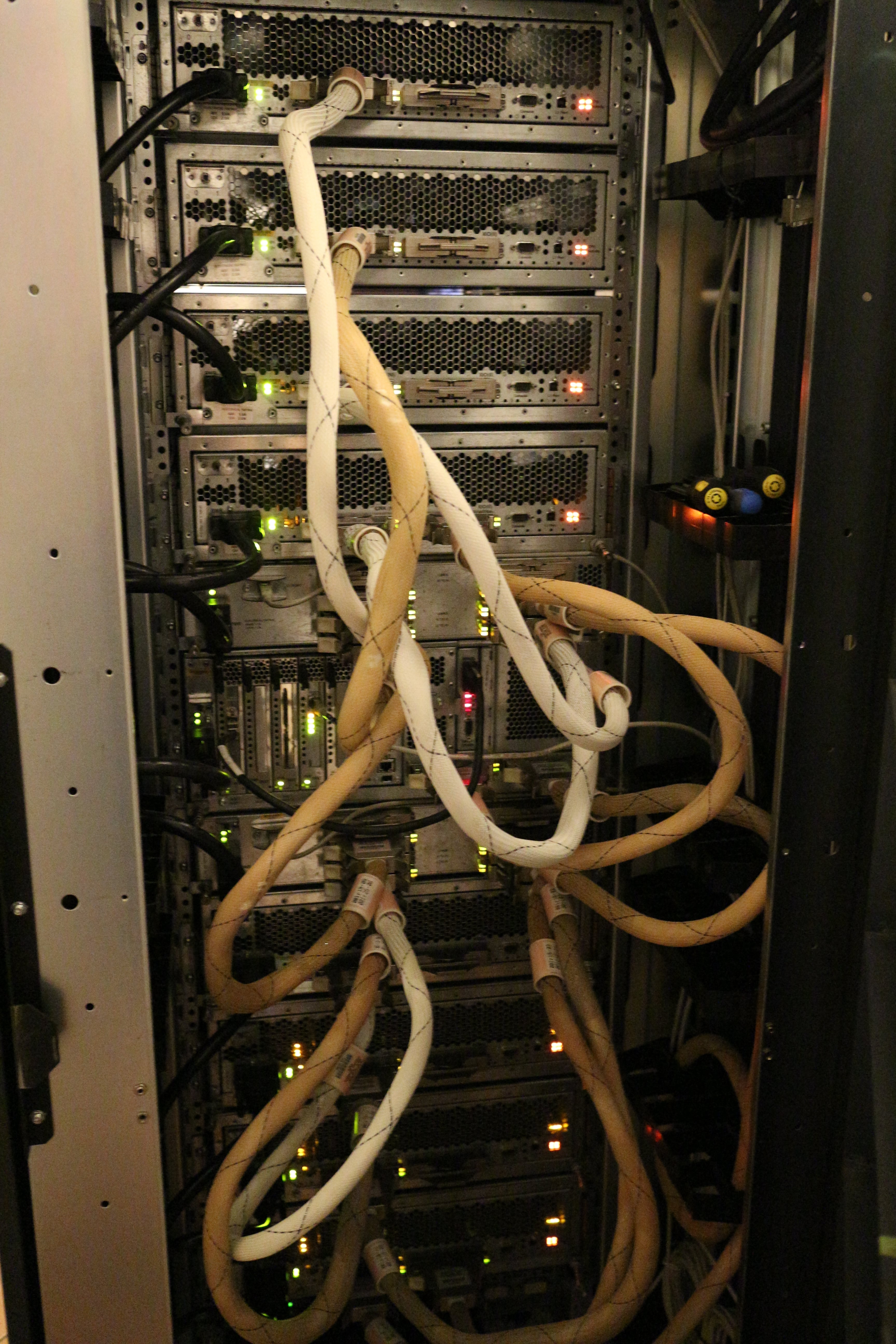
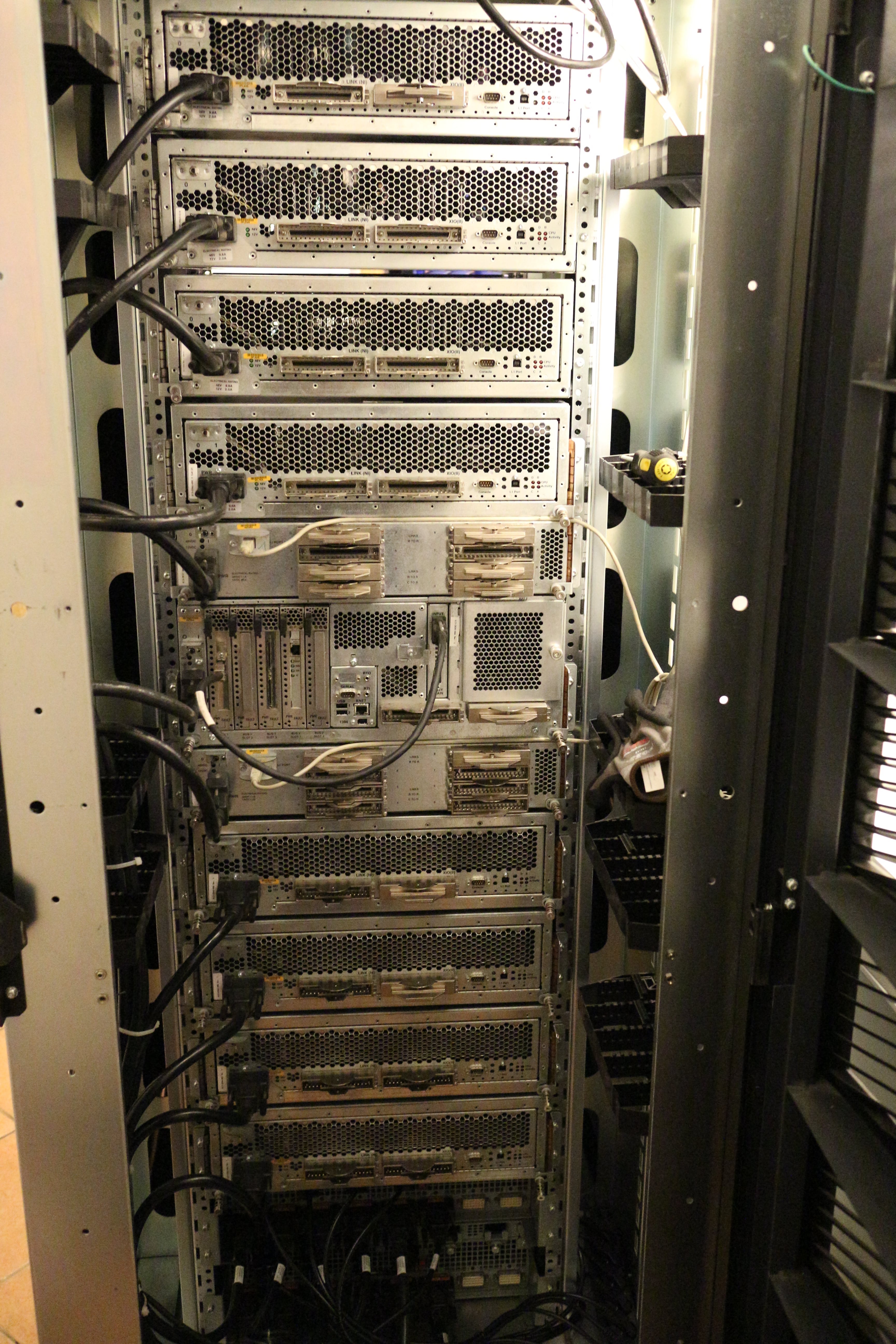


More pictures coming soon!
Documents ↵^
- SGI Origin 3000 Datasheet (PDF, 404kB)
- SGI Origin 3000 Series Owner's Guide (PDF, 11MB) — instructions on operating the machine and performing common hardware maintenance tasks.
- SGI L1 and L2 Controller Software User's Guide (PDF, 746kB) — instructions for interacting with the L1 and L2 controllers (with a list and descriptions of all the commands).
- SGI Origin 3000 Series Technical Configuration Owner's Guide (PDF, 3.3MB) — technical information about the various parts of the system, and configuration guidelines.
- SGI Origin 3000 Family Reference Guide (PDF, 5.1MB) — overview of the various bricks and available system configurations.
- SGI Origin 3000 System Architecture (PDF, 375kB) — detailed description of the Origin architecture.
- SGI Origin 3000 System Cabling Guide (PDF, 5.9MB) — shows you how to connect the bricks together.
- SGI Origin 3000 Site Planning Guide (PDF, 990kB) — shows you how to prepare a site for the Origin 3000 series systems.
- SGI Origin and Onyx2 Series Hardware Quick-Reference Booklet (PDF, 8.2MB) — this one is for the older Origin 2000 series machines, but still contains useful chapters that are applicable to the Origin 3000 series (e.g. POD mode commands).
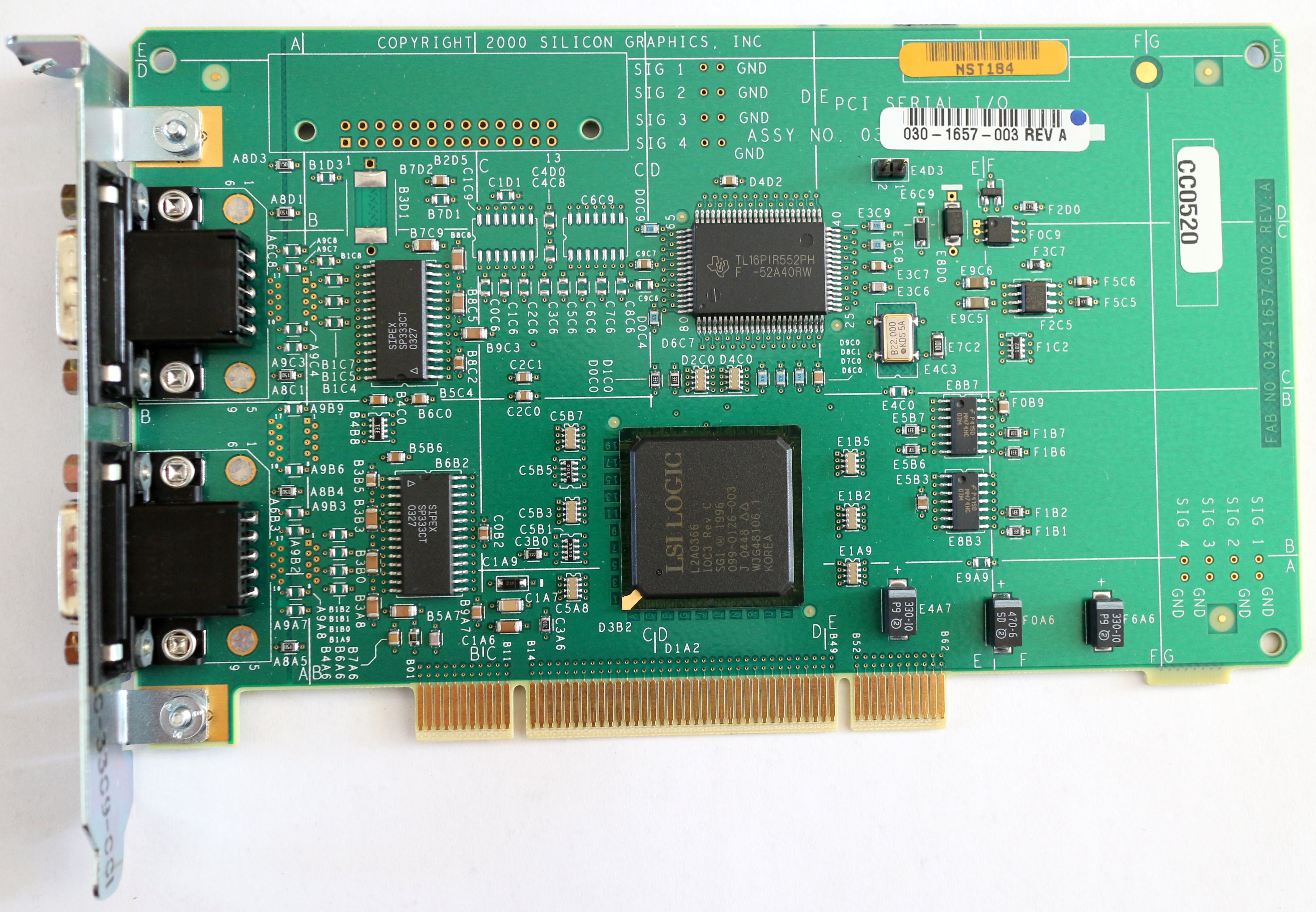
- SGI Gigabit Ethernet Board User's Guide (PDF, 873kB) — user's guide for SGI's first-generation gigabit ethernet PCI board.
- SGI Release 2 Gigabit Ethernet Board User's Guide (PDF, 896kB) — user's guide for SGI's second-generation gigabit ethernet PCI board.
- DPS Power Supply Specification V2.0 (PDF, 263kB) — general specification for the power supplies used in the Origin's power bay.
- DS1780E Datasheet (PDF, 337kB)
- HGST Ultrastar SSD400S FC-AL Enterprise SSD Datasheet (PDF, 321kB)
- HGST Ultrastar SSD400S FC-AL Enterprise SSD Specifications (PDF, 4.2MB)
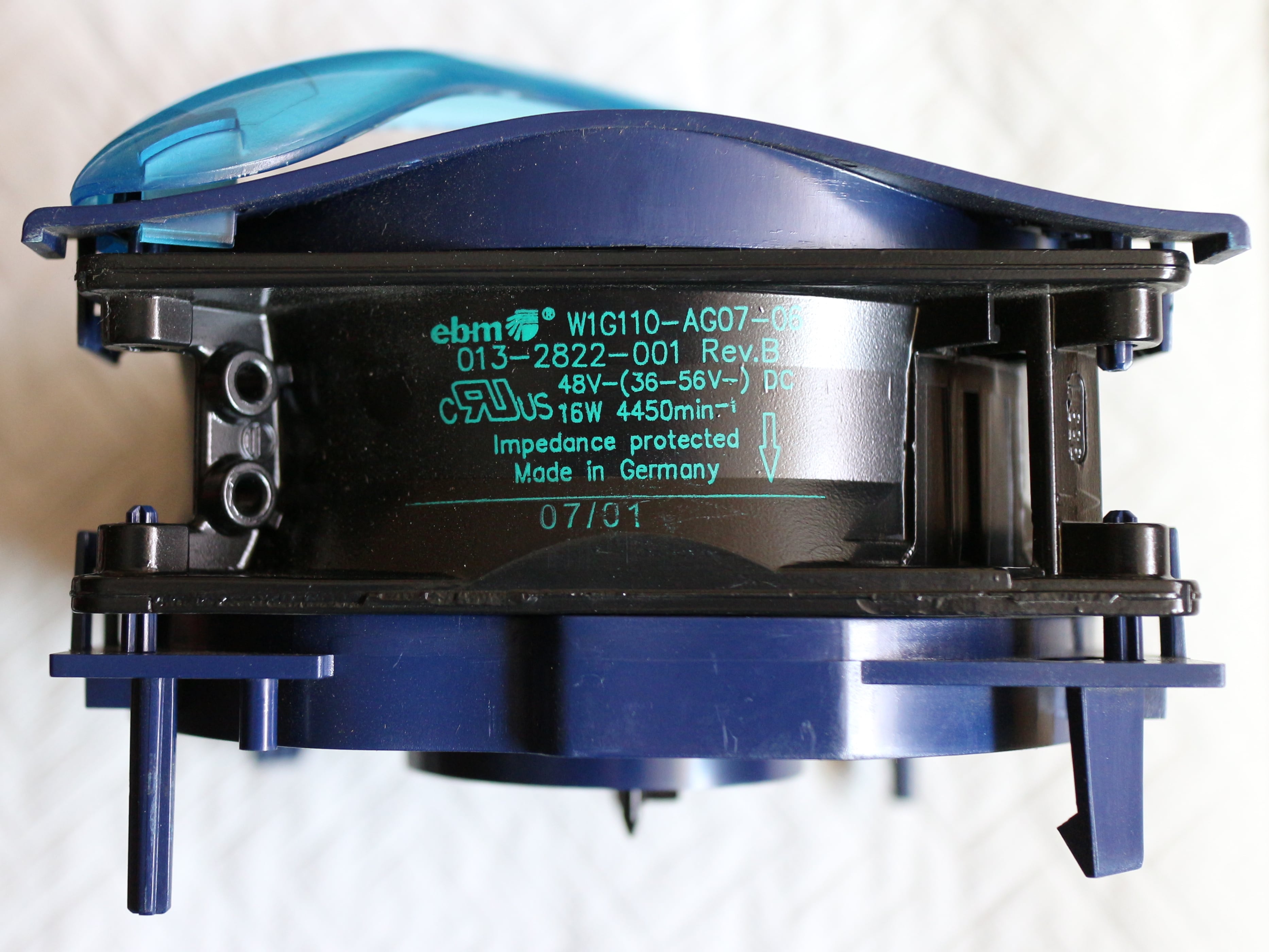
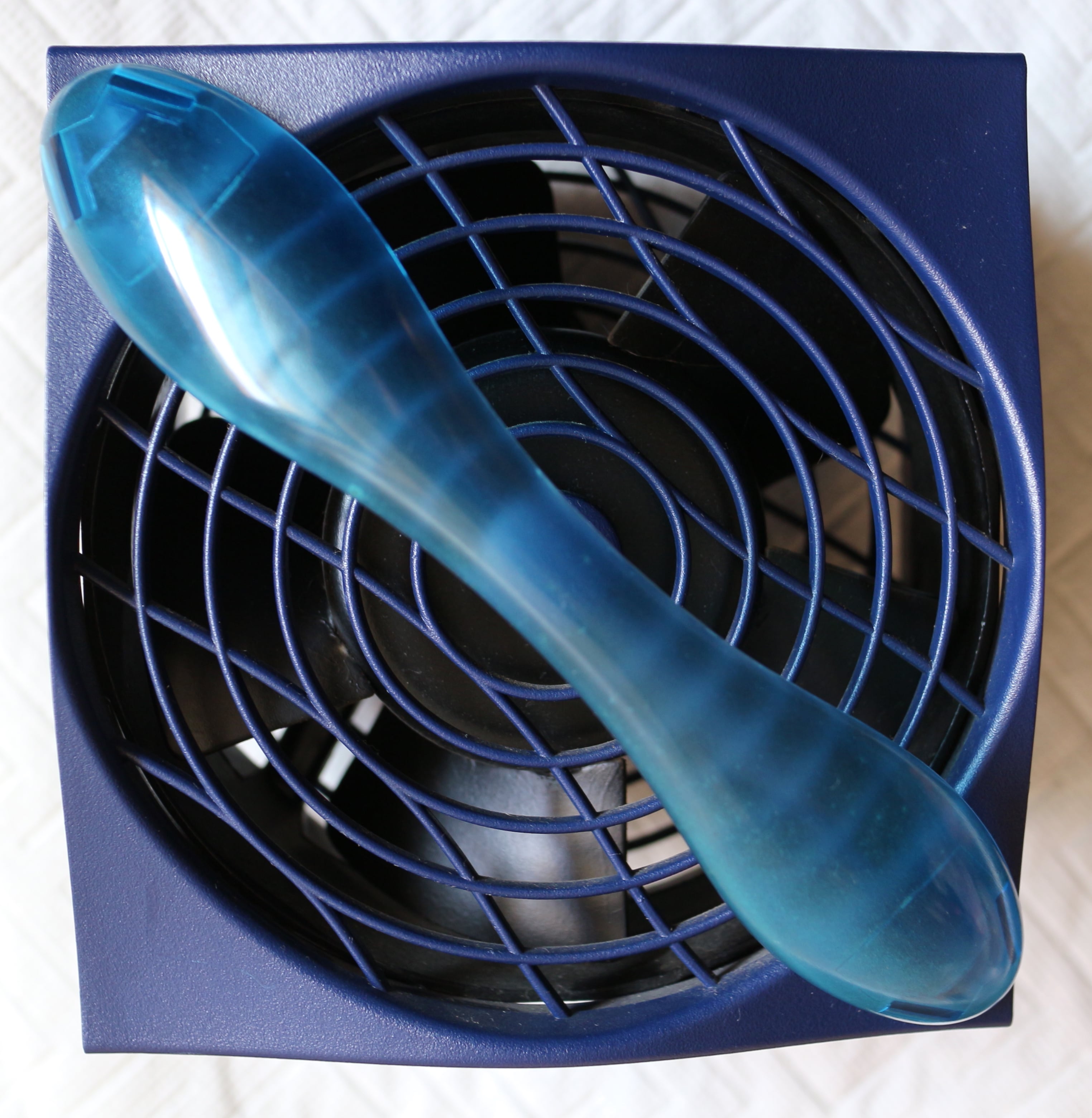
- EBM W1G110-AG07-06 fan datasheet (PDF, 340kB) — these are the large 48V fans used in bricks.
Acknowledgements ↵^
All diagrams/drawings on this page were taken from SGI manuals and other documentation.